Choosing the right CAD conversion service provider is crucial for businesses involved in mechanical engineering, architecture, and various other engineering design service. With the right partner, you can ensure that your CAD drawings are accurate, reliable, and delivered on time. In this guide, we’ll explore the essential factors to consider when selecting a CAD conversion service provider.
Understanding CAD Conversion Services
Before diving into the key considerations, it’s essential to understand what CAD drawing service entails. CAD conversion involves transforming paper-based drawings or other file formats into a digital CAD format. This process is vital for businesses looking to digitise their engineering designs, making them easier to store, edit, and share.
Key Considerations
1. Expertise and Experience
One of the key factors that an organization needs to consider when outsourcing CAD conversion services include the experience of the CAD conversion service provider. Reliable sources should be sought in the market for providers specializing in CAD drawing service. This research establishes that there is greater probability that highly experienced service providers are in a better position to comprehend various engineering design services and come up with correct solutions.
2. Range of Services Offered
A service provider should ideally be able to provide different services related to CAD such as CAD conversion, CAD drawing and all mechanical engineering service. By consolidating the different services in one company, this makes it easy for you to work with a single company providing those services to ensure that your designs are consistent.
3. Quality and Accuracy
The general quality and the extent of precision of the CAD drawings that have been converted is important. These inaccuracies result from differences between the paper drawings and the project and can be expensive in the further phases of your endeavors. Inquire about the providers’ quality control measures and ask them to submit the previous works they have done. Choose the providers that apply the latest software and utilize the experienced staff to obtain the highest quality of the final product.
4. Turnaround Time
Scheduling is one of the major factors that are usually put into consideration in engineering projects. So there is really a requirement for you to be specific with the turnaround time of your chosen CAD conversion service provider. Make sure they can deliver high quality work in the least possible time or within the time you set. Preliminary comparative discussion of the timing of your project’s work, selecting a provider that can at least meet the deadlines.
5. Cost-Effectiveness
Although quality should always be a top priority, one should also put into consideration a cost of CAD conversion services. Make sure you check the price in several brokers to make sure that the price given is reasonable. One should also avoid closely relating to providers who offer their services for much cheaper than the average price.
6. Data Security and Confidentiality
The engineering designs and drawings that you prepare are important tangible assets. Make sure that the quality of data security with the CAD conversion service provider is proper. To this the measures used are such as encrypted transfer, transfer of files with assurance that they will not be shared with any non-authorized personnel, and the use of non-disclosure agreements. This information should be well protected by any of the service providers you are selecting.
7. Customer Support
It is vital that there is proper customer support in any working relationship since it can sometimes be a deal breaker. Select CAD conversion service provider whose customer support is commendable as they should be in a position to promptly reply to the queries, give progress reports regarding the project as well as be in a position to work on any complication that may arise in the project.
8. Technology and Software
Since the role of the CAD conversion service provider is to convert the designs into an effective platform for manufacturing, then the technology and the software that they use in the conversion process significantly determines the quality of the final conversion. Request to know if the provider employs the most current CAD applications, and software system. This also enhances the quality of the conversions that are made although they also provide compatibility with your systems.
9. Customization and Flexibility
There are factors that are distinct to every project. A good CAD conversion service should be able to address your needs including issues of customization and flexibility. When it comes to such aspects as file format or any detail you would like to be included in the drawing, the provider should be willing to help.
10. References and Reviews
Last but not the least, verify the references of a provider, as well as read more on other clients’ accounts of the provider they hired. This can help provide a picture of the provider’s dependability, work quality, and communication with clients or consumers. The customers’ reviews and case studies can be found on the site or speak directly to the provider about the references.
Conclusion
Choosing the right CAD conversion service provider is a critical decision that can significantly impact the success of your engineering projects. At the same time, you can consider basic criteria like proficiency, the number and types of services offered, the quality and price, the speed of work, confidentiality, communication, use of advanced technologies, possibility of adaptation to the client’s needs, and recommendations.
Just keep in mind that an ideal provider apart from providing CAD drawings on your project will also minimise errors if any while at the same time being economically efficient in providing their services. Do not rush with the selection and make sure that you ask providers about necessary papers and can view some of their works. When it comes to engineering design, the choice of CAD conversion service provider determines the efficiency of the processes and results.
In the realm of engineering, manufacturing, and design, technical drawing stands as a cornerstone, facilitating communication and precision in translating ideas into tangible creations. From the traditional tools of the past to the advanced software of today, it has evolved to meet the demands of modern innovation. In this blog, we will learn the depths of technical drawing, exploring its various types, techniques, and applications.
What is Technical Drawing?
Technical drawing, also known as drafting or engineering Design, serves as a visual language for conveying complex information related to designs, specifications, and instructions. It acts as a bridge between engineers, designers, and manufacturers, providing a detailed roadmap for the creation and realisation of products, structures, and systems. Whether it’s a blueprint for a skyscraper or a schematic for an electronic circuit, it plays a crucial role in ensuring accuracy, clarity, and consistency throughout the design and production process.
Types of Technical Drawing
Orthographic Projection
Orthographic projection, the fundamental technique in technical drawing, involves representing three-dimensional objects in two dimensions. This method utilises multiple views, including front, top, side, and sectional views, to provide a comprehensive depiction of the object’s shape and dimensions. By presenting various perspectives, orthographic projection enables engineers and manufacturers to visualise and analyse the object from different angles, ensuring precise interpretation and execution.
Isometric Drawing
Isometric drawing offers a simplified yet realistic representation of three-dimensional objects. Unlike orthographic projection, which maintains strict geometric accuracy, isometric drawings depict objects at a 30-degree angle to the horizontal axes, providing an illusion of depth without distortion. This type of drawing is commonly used in architectural renderings, industrial product design, and technical illustrations, offering a visually appealing way to showcase complex structures and assemblies.
Perspective Drawing
Perspective drawing employs foreshortening and vanishing points to create realistic representations of objects as they appear in three-dimensional space. Unlike orthographic and isometric drawings, which focus on precise measurements, perspective drawings emphasise visual depth and realism. This technique is widely used in architectural visualisation, interior design, and artistic illustrations, allowing designers to convey spatial relationships and atmospheric effects with accuracy and flair.
Assembly drawing provides a detailed overview of how individual components fit together to form a larger assembly or product. It includes exploded views, part lists, and assembly instructions to guide the construction or manufacturing process. Assembly drawings are essential for ensuring proper alignment, fit, and functionality of mechanical and structural systems, serving as a blueprint for assembly and maintenance procedures.
Electrical Schematic Design & Drawing illustrates the connections and components of electrical circuits using standardised symbols. These drawings provide a visual guide for designing, troubleshooting, and repairing circuits in various applications, including electronics, automation, and power systems. Electrical schematics convey information such as component layout, wiring connections, and circuit functionality, enabling engineers and technicians to understand and manipulate electrical systems effectively.
Electrical Schematic Drawing
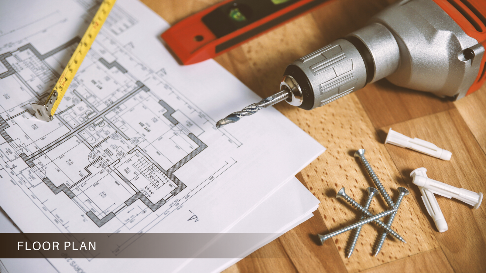
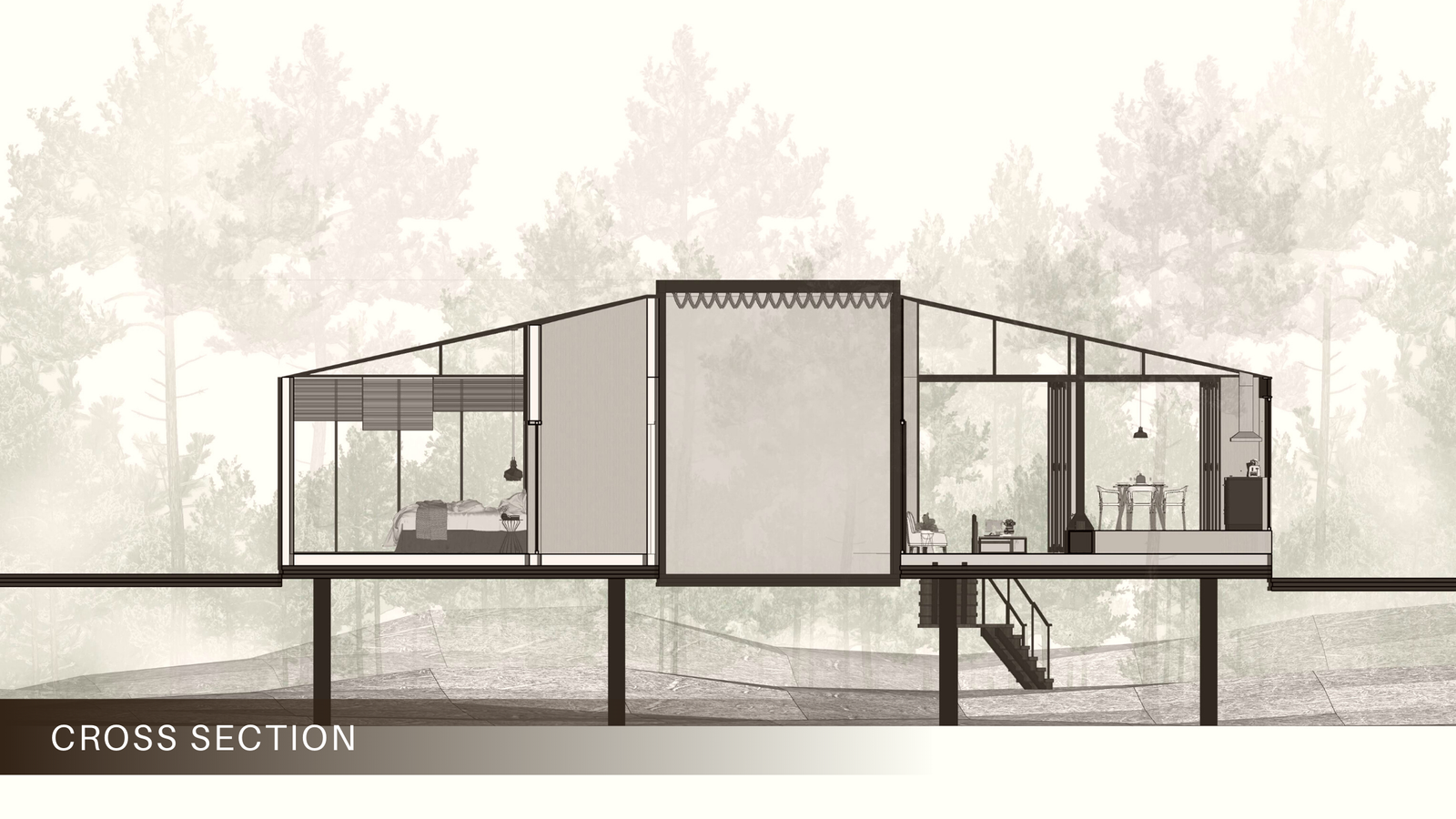
Architectural Drawing
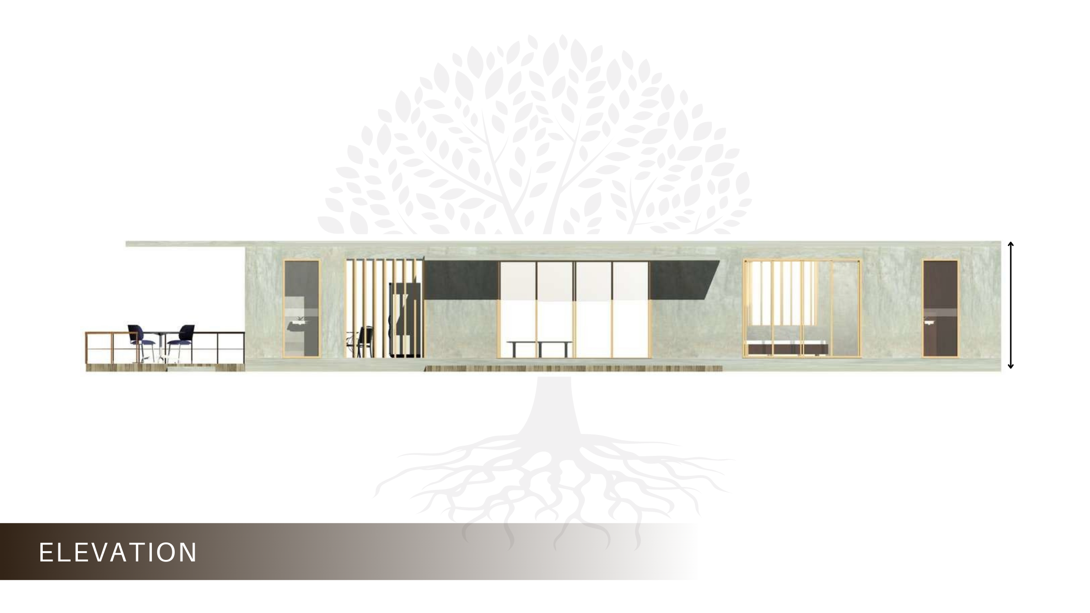
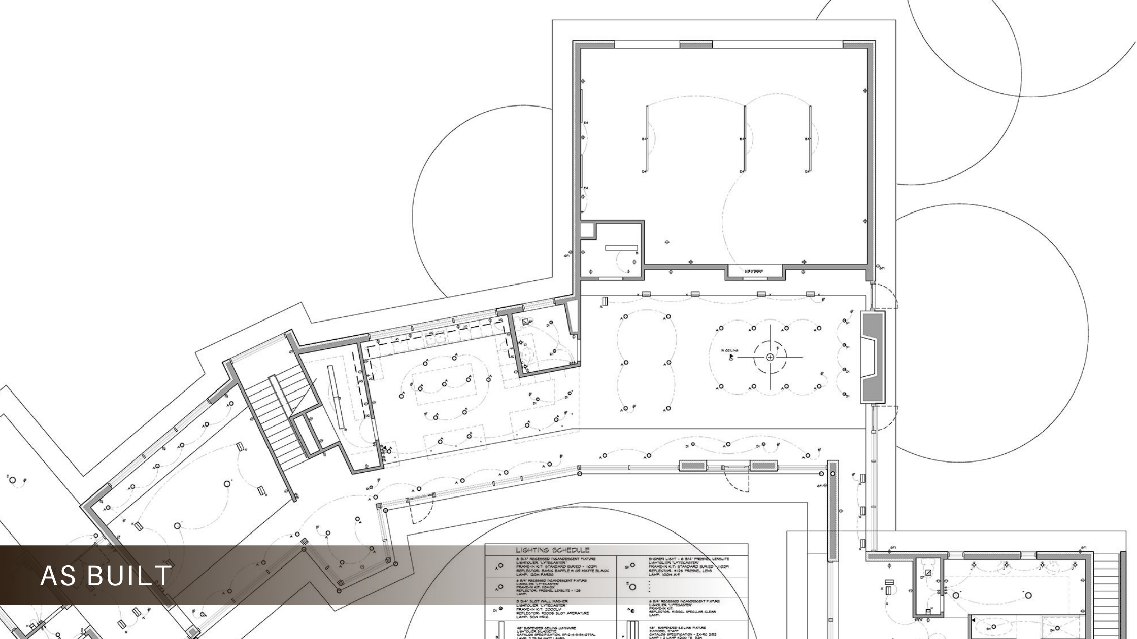
Architectural drawing encompasses a range of drawings used to design and construct buildings and structures. This includes floor plans, elevations, sections, and site plans, which communicate spatial relationships, dimensions, and aesthetic details. Architectural drawings serve as a communication tool between architects, engineers, contractors, and clients, guiding the entire building process from conception to occupancy.
Architectural Drawing
Techniques and Standards
The creation of technical drawings relies on various techniques and standards to ensure accuracy, consistency, and compatibility across different industries and applications. International organisations such as the International Organization for Standardization (ISO) and the American Society of Mechanical Engineers (ASME) establish guidelines and standards for technical drawing practices.
ISO 128 provides general rules for the execution of technical drawings, applicable to mechanical engineering, construction, architecture, and shipbuilding. It defines principles for line types, dimensioning, and notation, ensuring uniformity and clarity in technical communication.
ASME Y14.5 specifies standards for dimensioning and tolerancing, crucial aspects of technical drawing that ensure proper fit, form, and function of mechanical components. These standards help prevent errors and discrepancies in manufacturing processes, enhancing efficiency and quality control.
Applications and Industries
Technical drawing finds application across various industries, from aerospace and automotive engineering to electronics and construction. aerospace engineering, they are used to design aircraft components and systems, ensuring safety, performance, and regulatory compliance.
In automotive design and manufacturing, it plays a vital role in prototyping, tooling, and production processes, guiding the development of vehicles and their components from concept to assembly line.
In electronics and electrical engineering, technical drawings facilitate the design and assembly of circuits, control systems, and electronic devices, enabling innovation and advancement in technology.
construction and architecture, it informs the planning, construction, building design & drawing and infrastructure projects, providing detailed documentation of structural, mechanical, and electrical systems.
History of Technical Drawing
It has a rich history that dates back centuries, evolving alongside advancements in science, engineering, and architecture. The roots of technical drawing can be traced to ancient civilizations such as Mesopotamia, Egypt, and Greece, where early engineers and architects used rudimentary drawings to plan and construct monumental structures like pyramids and temples.
During the Renaissance period, artists and inventors like Leonardo da Vinci pioneered the use of detailed technical sketches to explore scientific principles and engineering concepts. Da Vinci’s notebooks are renowned for their intricate diagrams and illustrations, showcasing his visionary ideas and innovations in fields ranging from anatomy to aeronautics.
In the 19th century, the Industrial Revolution brought about significant advancements in technical drawing tools and techniques. The invention of mechanical pencils, ruling pens, and precision instruments enabled engineers and draughtsman to create highly accurate and detailed drawings with unprecedented efficiency.
The 20th century witnessed the emergence of computer-aided design (CAD) software, revolutionising the way technical drawings are created, edited, and shared. CAD technology, initially developed for aerospace and automotive industries, quickly proliferated across various sectors, offering designers and engineers powerful tools for digital drafting and modelling.
Today, it continues to evolve in tandem with digital technologies, with innovations such as 3D modelling, virtual reality (VR), and augmented reality (AR) reshaping the landscape of design and visualisation. Despite these advancements, the principles of technical drawing remain rooted in precision, clarity, and communication, serving as a timeless foundation for innovation and creativity.
Future Trends in Technical Drawing
As we look ahead, several trends and developments are poised to shape the future of technical drawing:
Integration of AI and Machine Learning: Artificial intelligence (AI) and machine learning algorithms are increasingly being incorporated into CAD software, enabling automated tasks such as dimensioning, pattern recognition, and design optimization. These intelligent features streamline the drafting process and enhance productivity, allowing designers to focus on higher-level tasks and creative problem-solving.
Cloud-Based Collaboration Platforms: Cloud-based collaboration platforms facilitate real-time collaboration and communication among dispersed teams of designers, engineers, and stakeholders. These platforms enable seamless sharing of technical drawings, feedback exchange, and version control, fostering efficient project management and decision-making.
Advancements in 3D Printing: The rapid advancement of 3D printing technology offers new possibilities for prototyping, manufacturing, and product development. Technical drawings play a crucial role in 3D printing workflows, providing the blueprint for creating intricate and functional objects layer by layer. As 3D printing evolves, its standards and practices will adapt to accommodate this disruptive technology.
Incorporation of Virtual and Augmented Reality: Virtual reality (VR) and augmented reality (AR) technologies are revolutionising the way designers visualise and interact with VR and AR applications allow users to immerse themselves in virtual environments, manipulate 3D models, and simulate real-world scenarios, enhancing design comprehension and user experience.
Sustainability and Green Design: With a growing emphasis on sustainability and environmental consciousness, its practices are evolving to prioritise eco-friendly design principles and materials.Concepts like life cycle assessment (LCA), cradle-to-cradle design, and biomimicry are influencing the conceptualization and execution of technical drawings, promoting responsible innovation and resource conservation.
Conclusion
Technical drawing is essential for turning ideas into reality in engineering, architecture, and manufacturing. Companies like Monarch Pvt. Ltd. lead the way with their commitment to innovation and excellence. By embracing new technologies and trends, they inspire progress and shape the future of technical drawing. Together, we can continue pushing boundaries and creating a brighter future for all.
FAQs
Q: What are the 5 parts of technical drawing?
A: The five main parts of a technical drawing are the title block, drawing border, main drawing (including views and details), dimensions, and annotations. These components collectively provide comprehensive information about the depicted object or structure.
Q: Is technical drawing difficult?
A: Technical drawing can be challenging initially due to its precision and requirement for attention to detail. However, with practice, patience, and proper guidance, mastering technical drawing becomes achievable for many individuals.
Q:Who uses technical drawings?
A: Engineers, architects, designers, manufacturers, and drafters extensively use technical drawings in their respective fields to convey precise information about objects and structures.
A: Technical drawings provide detailed visual information essential for communication, fabrication, and understanding of complex objects and structures.
MEP engineering encompasses the intricate planning, design, and management of Mechanical, Electrical, and Plumbing systems within buildings. These systems are the essential infrastructure that ensures the comfort, functionality, and efficiency of any structure. Mechanical systems regulate temperature and airflow, electrical systems provide power and lighting, while plumbing systems supply water and dispose of waste. MEP engineers work meticulously to integrate these systems seamlessly into the building’s architecture, considering factors like energy efficiency, sustainability, and compliance with building codes and regulations.
The Role of MEP Engineers
Roles like MEP engineering consultants play a pivotal role in the construction process, from conceptualization to completion. They collaborate closely with architects, structural engineers, and other stakeholders to develop holistic building design and drawings that meet the client’s requirements and objectives. By leveraging their expertise in mechanical, electrical, and plumbing systems, MEP engineers ensure that buildings are not only functional but also safe, reliable, and environmentally sustainable. Their responsibilities include system design, equipment selection, cost estimation, project management, and quality assurance.
Services Offered by MEP Engineering Firms
MEP engineering firms offer a comprehensive range of services to address the diverse needs of clients across various industries. These services encompass:
Mechanical Engineering: Designing HVAC systems, including heating, ventilation, and air conditioning, to maintain optimal indoor comfort and air quality.
Electrical Engineering: Planning and implementing electrical systems for power distribution, lighting, communication, and safety, ensuring reliable and efficient electrical infrastructure.
Plumbing Engineering: Developing water supply, drainage, and sewage systems, including fixtures, pipes, and pumps, to deliver clean water and manage wastewater effectively.
Additionally, MEP firms offer specialized services like energy management, sustainable design, commissioning, and building automation, enhancing building performance and sustainability.
The Benefits of Using MEP Services
Partnering with MEP Engineering Company offers numerous benefits for building owners, developers, and occupants alike. These benefits include:
Improved Energy Efficiency: MEP engineers employ innovative technologies and design strategies to minimise energy consumption and reduce operational costs over the building’s lifespan.
Enhanced Safety and Compliance: By adhering to building codes and regulations, MEP engineers ensure that building systems meet safety standards and regulatory requirements, mitigating risks and liabilities.
Cost Savings: Through efficient design, optimization of resources, and lifecycle analysis, MEP engineers help minimise construction costs and long-term operational expenses.
Optimal Performance: MEP engineers optimise building systems for performance, reliability, and resilience, ensuring seamless operation and minimal downtime.
Environmental Sustainability: By integrating sustainable design principles, renewable energy sources, and green building practices, MEP engineers contribute to reducing the environmental impact of buildings and promoting sustainability.
A Day in the Life of an MEP Engineer
The daily routine of an MEP engineer is dynamic and multifaceted, encompassing a wide range of tasks and responsibilities. A typical day may involve:
Collaborating with architects and other engineers to develop design concepts and project requirements.
Conducting site visits to assess existing conditions, coordinate with contractors, and inspect MEP installations.
Utilising computer-aided design (CAD) software to create detailed drawings, schematics, and specifications for MEP systems.
Performing calculations, simulations, and analyses to optimise system performance, efficiency, and cost-effectiveness.
Attending meetings with clients, contractors, and project teams to discuss progress, address challenges, and ensure project alignment.
Reviewing and approving shop drawings, submittals, and change orders to maintain project quality and compliance.
Throughout the project lifecycle, MEP engineers remain actively involved in all aspects of design, construction, and commissioning, leveraging their technical expertise and problem-solving skills to deliver successful outcomes.
How to Become an MEP Engineer
Becoming an MEP engineer requires a combination of education, training, certification, and practical experience. The typical path to becoming an MEP engineer includes:
Obtaining a bachelor’s degree in mechanical engineering, electrical engineering, or a related field from an accredited institution.
Gaining hands-on experience through internships, co-op programs, or entry-level positions in the engineering industry.
Pursuing professional licensure as a Professional Engineer (PE) or relevant certifications from recognized organisations such as the American Society of Heating, Refrigerating and Air-Conditioning Engineers (ASHRAE) or the National Fire Protection Association (NFPA).
Continuing education and professional development to stay current with industry trends, technologies, and regulations.
By continuously honing their skills and knowledge, aspiring MEP engineers can position themselves for rewarding careers in a dynamic and evolving field.
Choosing the Right MEP Engineering Partner
Selecting the right MEP engineering firm is crucial for the success of any construction project. When evaluating potential partners, consider the following factors:
Expertise and Experience: Look for firms with a proven track record of delivering high-quality MEP designs and solutions across a range of project types and industries.
Technical Competence: Assess the firm’s technical capabilities, including proficiency in relevant software, tools, and methodologies for MEP design and analysis.
Collaboration and Communication: Choose a partner that values collaboration, open communication, and teamwork, fostering a positive and productive working relationship.
Sustainability and Innovation: Priorities firms that demonstrate a commitment to sustainability, green building practices, and innovation in MEP design and technology.
Reputation and References: Seek recommendations, reviews, and references from previous clients, contractors, and industry professionals to gauge the firm’s reputation and reliability.
By selecting an MEP engineering partner that aligns with your project goals, values, and expectations, you can ensure a smooth and successful collaboration from inception to completion.
Conclusion
In conclusion, MEP engineering stands as the cornerstone of modern building design, seamlessly integrating mechanical, electrical, and plumbing systems to foster safe, comfortable, and efficient environments. At the forefront of this crucial discipline are companies like Monarch Innovation Private Limited, whose expertise, innovation, and dedication are instrumental in shaping the built environment and enhancing the quality of life for communities worldwide. Monarch Innovation showcases the crucial role MEP engineers play in construction, designing sustainable buildings, optimizing energy performance, and ensuring regulatory compliance. As we appreciate the seamless operation of the buildings we inhabit, let us acknowledge and commend the contributions of MEP engineers, with Monarch Innovation standing as a beacon of excellence in this field.
FAQs
Q: What does MEP stand for?
A: MEP stands for Mechanical, Electrical, and Plumbing engineering. It encompasses the design, installation, and maintenance of these systems in buildings.
Q:Why is MEP engineering important in construction?
A: MEP engineering ensures that buildings have functional heating, cooling, lighting, water supply, and drainage systems, enhancing occupant comfort and safety.
Q: What services do MEP firms typically provide?
A: MEP firms offer a range of services including system design, energy efficiency analysis, sustainability consulting, commissioning, and building automation solutions.
Q: What challenges do MEP engineers face in their work?
A: Challenges may include integrating complex systems, optimizing energy efficiency, managing project budgets and timelines, and addressing evolving technology and regulatory requirements.
Q: How can I find a reputable MEP engineering firm for my project?
A: Research online reviews, ask for referrals from colleagues or industry associations, and evaluate firms based on their experience, expertise, project portfolio, and commitment to sustainability.
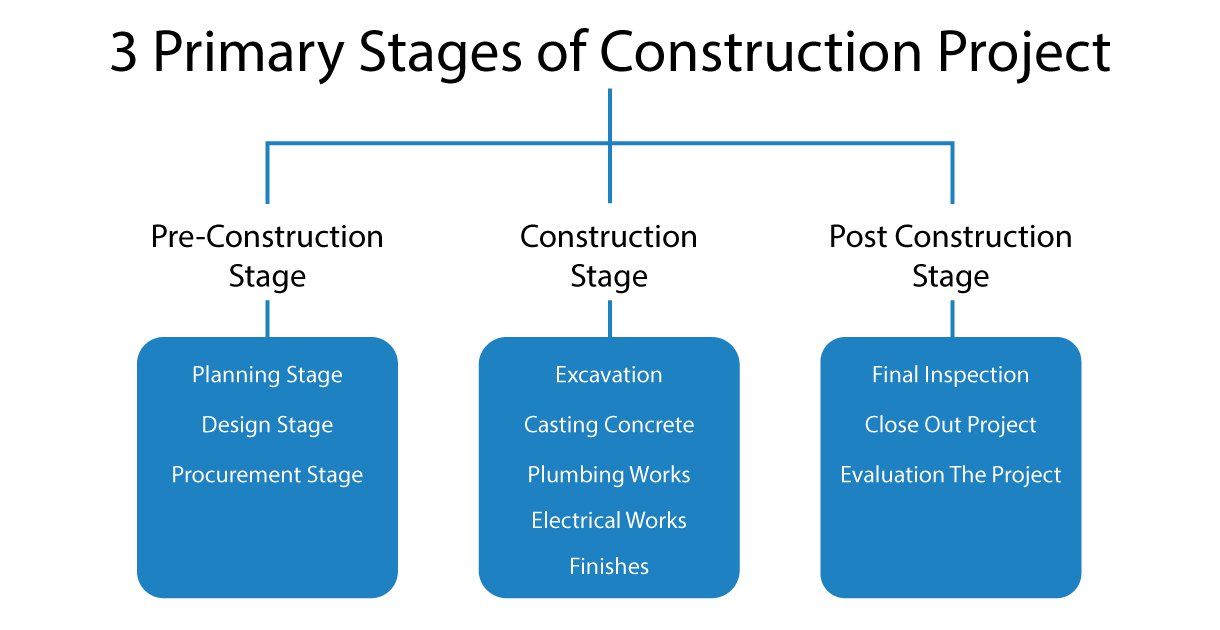
In the oil and gas industry, piping design plays a critical role in ensuring the safe and efficient transportation of hydrocarbons from the wellhead to the refinery or processing plant. The intricate network of pipelines that crisscross the globe is the backbone of this industry, and its design and construction require planning and execution. This is where the expertise of piping design engineers comes into play.
Piping Design: A Multifaceted Process
Piping design is a complex process that involves several stages, from conceptual design to detailed engineering. pipeline engineers work closely with other disciplines, such as process engineers, structural engineers, and material specialists, to ensure that the piping system meets the required specifications and adheres to industry standards and regulations.
The first step in pipeline design is the conceptual design phase, where the overall layout and routing of the pipelines are determined. This involves considering factors such as the location of the wellheads, processing facilities, and storage tanks, as well as the terrain and environmental conditions. During this phase, piping design engineers use their expertise to optimize the route, considering factors such as cost, safety, and accessibility.
Once the conceptual design is approved, the piping design engineer moves on to the detailed engineering phase. This involves creating 3D piping CAD drawings and models, which provide a comprehensive representation of the piping system, including all its components, such as valves, flanges, and supports. These 3D CAD models are essential for ensuring the accurate fabrication and installation of the piping system.
The Pivotal Role of Piping Design Engineers
Piping design engineers are highly skilled professionals who possess a deep understanding of materials science, fluid dynamics, and structural engineering principles. Their expertise is essential in selecting the appropriate materials, determining pipe sizes, and calculating pressure ratings to ensure the safe and reliable transportation of hydrocarbons.
Throughout the design process, piping engineers collaborate closely with other disciplines, such as process engineers, structural engineers, and material specialists, to ensure that the piping system meets all necessary specifications and adheres to industry standards and regulations.
The Advent of 3D Piping Design
One of the most significant advancements in piping design has been the introduction of 3D CAD modelling and drafting techniques. Traditional 2D drawings have given way to highly detailed and accurate 3DCAD drawings and models, which provide a comprehensive representation of the entire piping system, including all its components, such as valves, flanges, and supports.
The benefits of 3D piping design are numerous. These models enable engineers to perform clash detection analyses, identifying and resolving potential conflicts or interferences before construction begins. This proactive approach saves time, reduces costs, and minimises the risk of costly rework or delays during the installation phase.
Moreover, the 3D CAD model facilitates better collaboration and communication among project stakeholders. By providing a visual representation of the piping system, all parties involved can easily understand and provide feedback, leading to more efficient decision-making and problem-solving.
Piping Design and the Future of Energy
As the world transitions towards cleaner and more sustainable energy sources, the role of piping design in the oil and gas industry will continue to evolve. With the increasing focus on renewable energy sources, such as wind and solar, piping engineers will play a crucial role in the design and construction of the infrastructure required to transport and store these energy sources.
Additionally, the growing emphasis on carbon capture and storage (CCS) technologies will require extensive piping systems to transport and store captured carbon dioxide. Piping design engineers will be instrumental in designing these complex systems, ensuring their safe and efficient operation.
Conclusion
Piping design and drafting play an indispensable role in the oil and gas industry. From conceptual design to detailed engineering, piping design engineers play a vital role in ensuring hydrocarbons’ safe and efficient transportation. The advent of 3D piping design and the availability of specialised piping design services have further enhanced the industry’s capabilities, enabling more accurate and efficient project execution.
The expertise of piping engineers will be in high demand, not only in the oil and gas industry but also in the emerging renewable energy and carbon capture sectors. By staying at the forefront of technological advancements and industry best practices, piping design engineers will continue to play a pivotal role in shaping the future of energy production and distribution.
Get in touch with Monarch Innovation if you need someone to oversee all project requirements and offer creative, reliable solutions that will greatly boost your business’s potential for future growth. Monarch Innovation provides tailored solutions to assist clients in re-engineering their production processes to maximise their organisation’s productivity and efficacy.
FAQs
Q: What is piping design?
A: Piping design involves planning and creating the layout of pipes to transport fluids in industrial settings like oil and gas facilities.
Q: What is the difference between oil and gas pipelines?
A: Oil pipelines primarily transport crude oil and refined petroleum products, while gas pipelines transport natural gas and sometimes other gases like hydrogen or carbon dioxide. Oil pipelines often operate at lower pressures compared to gas pipelines due to differences in fluid properties.
Q: Which pipe is used in the oil and gas industry?
A: Various types of pipes are used in the oil and gas industry, including carbon steel pipes, stainless steel pipes, and alloy steel pipes. The selection depends on factors such as fluid properties, operating conditions, corrosion resistance, and budget constraints. Additionally, specialized pipes like seamless and welded pipes are employed based on project requirements.
Q: What are the challenges faced in piping design for oil and gas projects?
A: Challenges in piping design for oil and gas projects involve accommodating complex layouts, managing high pressures and temperatures, addressing corrosion and erosion, and ensuring compliance with diverse regulations.
Q: What are the components of oil and gas piping?
A: Components of oil and gas piping systems typically include pipes, fittings (such as elbows, tees, reducers), valves, flanges, supports, expansion joints, and instrumentation for monitoring and control.
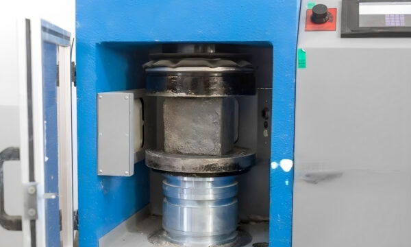
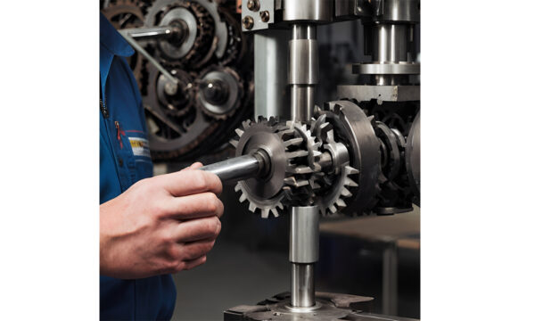
In the world of engineering and material science, mechanical testing plays a crucial role in evaluating the mechanical properties of materials. Mechanical testing is like giving materials a check-up to determine the strength of materials to evaluate their durability, mechanical testing serves as a fundamental tool for engineers. It helps engineers understand how materials will behave in different situations, so they can make sure everything from buildings to cars to everyday objects is safe and reliable. In this guide, we’ll explore the What is mechanical testing, its importance, and the different types of mechanical testing used to measure different properties of materials.
What is Mechanical Testing?
Mechanical testing is a process used to evaluate the mechanical properties of materials, providing valuable insights into how they will perform under various conditions. These properties include strength, hardness, elasticity, toughness, and more. By subjecting materials to controlled tests, engineers can understand their behaviour and make informed decisions in material selection, design, and manufacturing processes.
Types of Mechanical Testing
Tensile Testing:
Tensile testing is a type of mechanical testing used to understand how strong and stretchy material is. Imagine you have a rubber band, and you want to know how much you can stretch it before it breaks. That’s what tensile testing does but with all sorts of materials like metal, plastic, or fabric.
During the test, a small piece of the material, called a specimen, is pulled apart with a machine. As the machine pulls, it measures how much force is needed to stretch the material and how much the material stretches. This helps engineers figure out important things like how strong the material is (its strength) and how much it can stretch before breaking (its elasticity).
Tensile testing is crucial because it helps engineers choose the right materials for building things like bridges, airplanes, or even everyday items like chairs and tables. It ensures that these materials can handle the stresses they’ll face in real-life situations, keeping us safe and secure.
Tensile Testing
For example,
let’s say you’re designing a bridge. You’d want to know how strong the steel cables are that hold the bridge up. Tensile testing helps engineers figure out if the cables can handle the weight of cars and trucks driving over the bridge without snapping.
Common standards for the tensile test include ASTM E8/E8M (Standard Test Methods for Tension Testing of Metallic Materials), ISO 6892-1 (Metallic Materials), ASTM D638(Standard Test Method for Tensile Properties of Plastics), ASTM D412(Vulcanized Rubber and Thermoplastic Elastomers)
Compression Testing:
Compression testing applies force to compress a material, measuring its ability to withstand crushing forces. It’s commonly used to assess the compressive strength and stiffness of materials.
Here’s how it works: Imagine you have a block of foam. You place the foam block between two plates in a machine. Then, the machine pushes the plates together, applying more and more force until the foam squishes.
As the machine pushes, it measures how much force is needed to crush the foam and how much the foam squishes. This tells us important things about the material, like its compressive strength (how much force it can take before being crushed) and its stiffness (how much it resists being squished).
Compressive Testing
For example,
in construction, engineers might use compression testing to make sure concrete blocks are strong enough to support the weight of a building without crumbling under pressure.
Common standards for the Compression test include ASTM E9(Test Methods of Compression Testing of Metallic Materials at Room Temperature), ASTM D695(Test Method for Compressive Properties of Rigid Plastics), ASTM D1621(Compressive Properties of Rigid Cellular Plastics), BS EN ISO 604(Plastics – Determination of Compressive Properties)
Fracture Mechanics Testing
Fracture mechanics testing is like detective work for materials. It helps engineers understand how materials break and why. Imagine you’re investigating a crime scene where something broke – maybe a bridge, a car part, or even a simple household item. Fracture mechanics testing helps engineers figure out what caused the break and how to prevent it from happening again.
Fracture Mechanics Testing
Here’s how it works: Engineers take a broken piece of material and examine it closely, like a detective looking for clues. They might use special tools to measure things like the size and shape of the crack, how fast it grew, and what direction it spread. This information helps them understand the material’s behaviour under stress and identify any weaknesses or flaws that led to the break.
By studying fractures in this way, engineers can improve designs, choose better materials, and make products safer and more reliable. It’s like solving a mystery to protect people and property from future accidents.
Common standard for the Fracture Mechanics Testing includes ASTM E399, ASTM E1820, ASTM E1921, ASTM E1823, ASTM D5045, ISO 12135
Flexural Testing:
Flexural testing, also known as bend testing, is like giving a material a gentle bend to see how flexible and strong it is. It’s a mechanical test used to measure a material’s resistance to bending or flexing.
Flexural Testing
Here’s how it works: Imagine you have a thin piece of wood or a plastic ruler. You place it across two supports, like a mini bridge, and apply a force to the middle of the ruler. As you push down, the ruler bends or flexes and the machine measures how much it bends and how much force it takes to bend it.
Flexural testing helps engineers understand how materials behave when subjected to bending forces, which is important for designing things like beams, bridges, or even everyday items like plastic containers or metal rods. By knowing how much a material can bend before breaking, engineers can design structures and products that are strong and durable enough for their intended use.
Common standard for the Flexural Testing includes ASTM D790, ASTM C1161, ASTM D6272
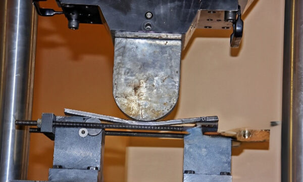
Impact Testing
Impact testing is like giving a material a sudden hit or shock to see how it reacts. It’s a mechanical test used to measure a material’s ability to absorb energy when subjected to sudden impact or shock loads.
Impact Testing
Here’s how it works: You have a material, like a metal or plastic sample, and you give it a quick hit with a swinging hammer or a falling weight. The test measures how much energy the material can absorb before breaking or cracking.
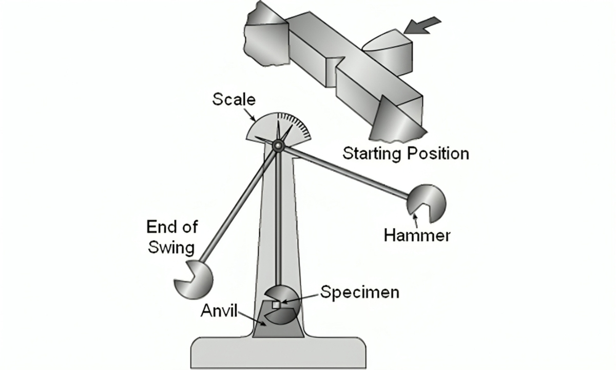
Common types of impact testing include:
Charpy Impact Test: Imagine swinging a small hammer at a notched piece of metal. The Charpy test measures how much energy the metal can absorb before breaking. It’s like checking how tough the metal is when hit.
Izod Impact Test: Similar to Charpy, but the metal piece is held vertically. It helps see how much energy the metal can absorb when struck differently.
Impact testing helps engineers understand how materials behave when they’re hit or bumped, which is important for designing things like car bumpers, helmets, or even smartphone cases. By knowing how much energy a material can absorb before breaking, engineers can design products that protect people and objects from impacts and accidents.
Common standard for the Flexural Testing includes ASTM E23, ASTM D256, ISO 179
Hardness Testing
Hardness testing is like giving a material a “toughness check” It helps engineers understand how resistant a material is to being scratched, indented, or deformed. Imagine you’re testing how hard a diamond is compared to a piece of wood – that’s where hardness testing comes in.
Hardness Testing
Here’s how it works: You have a small sample of the material, and you apply a known amount of force to it using a special tool, like a pointed tip or a small ball. The test measures how much the material resists being penetrated or deformed under this force.
Types of Hardness Testing, including:
Rockwell Hardness Test: In this test, a hard indenter is pressed into the material under a specific load, and the depth of indentation is measured. The Rockwell hardness is indicated by a numerical value on a scale.
Rockwell Hardness Test
Brinell Hardness Test: A hardened steel ball is pressed into the material under a specified load, and the diameter of the indentation is measured. Brinell hardness is calculated based on the applied load and the diameter of the indentation.
Brinell Hardness Testing Machine
Vickers Hardness Test: Like the Brinell test, but a square-based pyramid-shaped diamond is used as the indenter. Vickers hardness is determined by measuring the diagonal lengths of the indentation.
Mohs Hardness Scale: This scale ranks materials from softest to hardest based on their scratch resistance. For example, talc is the softest at 1, whereas diamond is the hardest at 10.
Knoop Hardness Test: Like the Vickers test, but a diamond indenter with a rhombic-based pyramid shape is used. Knoop hardness is calculated based on the applied load and the length of the indentation.
Each type of hardness test has its advantages and is suitable for different materials and applications. By performing hardness testing, engineers can ensure that materials meet the required specifications and are suitable for their intended use.
A common standard for Hardness Testing includes ASTM E10, ASTM E384, ISO 6508, and ISO 6506.
Fatigue Testing
Fatigue testing is like giving a material a “tiredness check.” It helps engineers understand how a material behaves when it’s repeatedly stressed or loaded repeatedly. Imagine you’re bending a paperclip back and forth until it breaks – that’s a bit like what fatigue testing does but on a larger scale for different materials.
Fatigue Testing
Here’s how it works: You take a sample of the material, like a metal rod or a plastic part, and you apply loads to it in a repetitive way. This could be bending, stretching, or compressing the material repeatedly. The test measures how many cycles the material can endure before it breaks.
Fatigue testing is crucial for things that go through a lot of stress in their lifetime, like aeroplane wings, car parts, or even the springs in your mattress. By understanding how a material holds up under repeated stress, engineers can design products that last longer and are less likely to fail over time.
Common standard for the Fatigue Testing includes ASTM E466, ASTM E606 / E606M, ASTM E647, ISO 1099, ISO 12107
Torsion Testing
Torsion testing is like twisting something to see how it holds up. It helps engineers understand how materials react when they’re twisted or torqued. Imagine you’re twisting a wet towel to wring out the water – that’s like what torsion testing does but on different materials.
Torsion Testing
Here’s how it works: You take a sample of the material, like a metal rod or a plastic tube, and you apply a twisting force to it. The test measures how much the material twists and how it responds to the force.
Torsion testing is crucial for things like shafts, screws, and gears that experience twisting forces in real-world applications. By understanding how a material responds to torsion, engineers can design stronger and more durable products that can handle twisting without breaking or deforming.
A common standard for Torsion Testing includes ASTM E1434, ISO 7800, and ISO 16803.
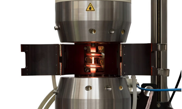
Creep Testing
Creep testing is like checking how a material slowly changes shape over time when it’s under constant stress. It helps engineers understand how materials behave when they’re exposed to prolonged loads or stress. Imagine you’re stretching a rubber band and watching how it gradually gets longer – that’s a bit like what creep testing does but for different materials.
Creep Testing
Here’s how it works: You take a sample of the material, like a metal rod or a plastic sheet, and you apply a constant load or stress to it. Then, you observe how the material deforms or stretches over a long period.
Creep testing is important for materials used in situations where they’ll be under constant stress for extended periods, like bridges, pipelines, or turbine blades. By understanding how a material responds to long-term stress, engineers can create structures and products that are safe and reliable over time.
A common standard for Creep Testing includes ASTM E1450, ASTM E292, and ISO 204.
Corrosion Resistance
Corrosion resistance is like giving a material a “rust check.” It measures how well a material can withstand damage caused by chemical reactions to its environment, like rusting or corroding.
Corrosion Resistance
Here’s how it works: When materials are exposed to things like moisture, salt, acids, or other corrosive substances, they can start to break down and deteriorate. Corrosion resistance testing evaluates how resistant a material is to these processes. It might involve exposing a sample of the material to harsh conditions for a set period and then assessing any damage or changes that occur.
Corrosion resistance is critical for materials used in environments where corrosion is likely to occur, like outdoor structures, pipelines, or marine equipment. By selecting materials with good corrosion resistance, engineers can ensure that products last longer and require less maintenance over time.
Common standard for the Corrosion resistance Testing includes ASTM G31, ASTM G71, ASTM B117, ISO 9227, ISO 9223
Non-destructive testing
Non-destructive testing (NDT) is like giving a material a “health check” without harming it. It’s a way to inspect and evaluate materials, components, or structures for defects or irregularities without causing damage.
Non-destructive testing
Here’s how it works: Instead of breaking apart or altering the material, NDT methods use various techniques to examine its properties and detect flaws. These techniques can include visual inspection, ultrasonic testing, radiographic testing, magnetic particle testing, and many others.
NDT is crucial for ensuring the safety, reliability, and quality of products and structures in industries like aerospace, automotive, construction, and manufacturing. By identifying defects early without damaging the material, engineers can make informed decisions about repair, maintenance, or replacement, ultimately saving time and costs.
Common standards for Non-destructive testing include Ultrasonic Testing (UT), Radiographic Testing (RT), Magnetic Particle Testing (MT), Liquid Penetrant Testing (PT)
What is the Importance of Mechanical Testing?
Mechanical testing is super important because it helps us understand how different materials will perform in real life.
That’s where mechanical testing comes in. By putting materials through tests like pulling them apart, squishing them, bending them, or hitting them, we can figure out how strong they are, how much they can bend, or how they’ll react to being hit.
Mechanical Testing helps engineers:
Choosing Materials: Engineers need to pick the right materials for their projects. Mechanical testing tells them how strong, flexible, or tough materials are, so they can choose the best ones.
Making Designs Better: By testing materials, engineers can figure out how to make designs stronger, safer, and more reliable. For example, they can make sure bridges can hold up heavy trucks or that airplane wings won’t break during flight.
Checking Quality: Mechanical testing helps engineers make sure that materials and products are made well. They can test samples to make sure they meet quality standards and are safe to use.
Understanding Failures: If something breaks unexpectedly, engineers can use mechanical testing to figure out why. This helps them fix problems and make things better next time.
Product Development: When developing new products or prototypes, engineers use mechanical testing to assess the performance and durability of different materials and designs. This ensures that the final product will meet or exceed customer expectations.
Compliance with Standards: Many industries have specific standards and regulations that materials and products must meet. Mechanical testing helps engineers ensure that their designs and materials comply with these standards, ensuring safety and regulatory compliance.
Cost Efficiency: By accurately predicting how materials will behave in real-world conditions, engineers can avoid over-engineering (using more material than necessary) or under-engineering (using inadequate materials), leading to cost-effective solutions.
This information is crucial for engineers, it helps them choose the right materials for different jobs, make sure products are safe, and even improve designs to make things better and stronger. So, mechanical testing helps us build safer, more reliable stuff!
In conclusion,
Understanding mechanical testing and its various types is crucial for ensuring the quality and durability of materials we use every day. Whether it’s checking how strong a metal is or making sure a plastic component can handle repeated stress, these tests help create safer and more reliable products.
If you’re looking for the Best mechanical testing services, consider reaching out to Monarch Innovation. Their expertise in mechanical testing can provide valuable insights into the performance and reliability of materials, ensuring that your products meet the highest standards. Invest in quality testing to build a stronger and more resilient future!
FAQs
Q: Why is Mechanical Testing important?
A: Mechanical testing is important because it helps ensure the quality, safety, and reliability of materials used in products and structures. It allows engineers to understand how materials will perform in real-world situations.
Q: What are the different types of mechanical testing?
A: The main types of mechanical testing include tensile testing, hardness testing, impact testing, fatigue testing, and corrosion resistance testing.
Q: How is mechanical testing done?
A: Mechanical testing is conducted by applying controlled forces to materials using specialized equipment. The process involves preparing specimens, applying loads, collecting data, analyzing results, and documenting findings.
Q: Where can I find reliable mechanical testing services?
A: Monarch Innovation offers comprehensive mechanical testing services to help businesses assess the properties and performance of materials used in their products.
In the complex world of product development, where innovation is the driving force, two dynamic disciplines, Industrial Design and Mechanical Engineering, play pivotal roles. These two fields, seemingly distinct, come together to shape the products we interact with every day. In this comprehensive exploration, we will delve into the differences between Industrial Design and Mechanical Engineering, supported by real-world examples. Moreover, we will introduce you to Monarch Innovation, your trusted partner in achieving the perfect balance between aesthetics and functionality.
Industrial Design: Where Art and Utility Converge
Industrial design is the creative heart of product development, blending aesthetics and functionality. Drawing from principles of ergonomics and unbounded creativity, industrial designers craft products that are not just practical but also visually captivating. They often follow an outside-in approach, prioritizing user experience and aesthetics.
Example: Think of the iPhone—a marvel of industrial design. Its sleek, user-friendly design and seamless integration of technology epitomize user-centric principles. Apple’s unwavering commitment to design has made its products iconic.
Computer-Aided Design (CAD): Precision in the Digital Realm
CAD (Computer-Aided Design) serves as the digital realm where engineers and designers transform abstract concepts into precise, three-dimensional models. This versatile tool is akin to a craftsperson’s toolkit, used to give life to intricate ideas.
Example: The Burj Khalifa, the world’s tallest skyscraper, heavily relied on CAD technology. It allowed engineers and architects to meticulously plan and execute the complex geometries and structural elements of the building.
Mechanical Engineering: The Science of Functionality and Reliability
Mechanical engineering forms the backbone of functionality and reliability. Rooted in scientific principles, mechanical engineers comprehend how objects respond to various forces and conditions. In the realm of product design, they take an inside-out approach, prioritizing performance, reliability, and manufacturability.
Example: The Boeing 787 Dreamliner showcases the prowess of mechanical engineering. Advanced materials, aerodynamic design, and innovative systems ensure fuel efficiency, reliability, and passenger comfort.
Choosing the Right Path: Project-Driven Decision
In today’s multifaceted landscape, industrial design firms may encompass mechanical expertise, while mechanical engineering company may house design-savvy professionals. CAD administrators often serve as versatile bridge builders, wielding the technical acumen needed to transform abstract ideas into tangible reality.
Example: When designing a high-end sports car, aesthetic appeal reigns supreme. Manufacturers like Ferrari engage industrial designers to craft visually stunning vehicles. However, beneath the surface, mechanical engineers ensure the car’s engine, suspension, and other components deliver top-tier performance and safety.
Pros and Cons: Industrial Design vs. Mechanical Engineering
Industrial Design:
Pros:
Aesthetic Excellence: Industrial design prioritizes aesthetics, resulting in visually captivating and user-friendly products.
Innovation: Industrial designers push creative boundaries, leading to groundbreaking concepts that capture attention.
Risk of Impracticality: Pursuing aesthetics and innovation may lead to challenging manufacturing processes and increased production costs.
Limited Focus: Industrial design may prioritize form over function, potentially overlooking critical engineering considerations.
Subjectivity: Aesthetic preferences vary widely, making it challenging to create universally appealing designs.
Mechanical Engineering:
Pros:
Functional Excellence: Mechanical engineering ensures products perform reliably and efficiently under various conditions.
Reliability: Rigorous testing and analysis lead to product durability, reducing failures and recalls.
Manufacturability: Mechanical engineers consider ease of manufacturing, leading to cost-effective production processes.
Cons:
Aesthetic Sacrifice: Mechanical engineering may prioritize function over form, potentially resulting in aesthetically lacking products.
Less Innovation in Form: A strong focus on functionality may stifle creativity in product aesthetics, leading to a lack of differentiation.
Complexity: Meticulous engineering can lead to longer design and development timelines.
Conclusion: Achieving the perfect balance
The distinctions between industrial design and mechanical engineering are not mere technicalities but the pillars upon which product development stands. It’s a world where creativity and precision converge, and the unique needs of your project should guide your choice.
In an ideal scenario, collaboration between industrial designers and mechanical engineers strikes a harmonious balance, resulting in products that excel in both form and function.
This is where Monarch Innovation, your trusted partner, comes into play.
Monarch Innovation is more than a company; it’s your trusted partner in crafting the perfect blend of aesthetics and functionality. With a team of seasoned professionals and cutting-edge resources, Monarch Innovation redefines the boundaries of what’s possible in design and engineering.
With Monarch Innovation by your side, you can seamlessly integrate the artistry of industrial design with the precision of mechanical engineering to breathe life into your vision.
In this intricate symphony of creativity and precision, Monarch Innovation is the conductor, orchestrating your journey toward innovative excellence. As you embark on your path of product development, Monarch Innovation is poised to illuminate your way, ensuring your vision becomes a reality where aesthetics and functionality coexist harmoniously.
FAQs
Can a mechanical engineer do industrial design?
Yes, a mechanical engineer can transition into industrial design with additional training in creative design principles and aesthetics. Many engineers successfully cross over into industrial design roles.
Is industrial design the same as mechanical engineering?
No, industrial design and mechanical engineering are distinct fields. Industrial design focuses on aesthetics, user experience, and form, while mechanical engineering deals with the technical aspects of product functionality and structural design.
What does mechanical & industrial engineering do?
Mechanical engineering involves designing, analyzing, and developing mechanical systems, machines, and devices, while industrial engineering optimizes processes, systems, and workflows to improve efficiency and productivity in various industries.
Can I be an industrial designer with an engineering degree?
Yes, having an engineering degree can be a valuable asset in industrial design, as it provides a strong foundation in problem-solving and technical understanding. Many industrial designers hold engineering degrees or have engineering backgrounds. Additional training in design principles may be necessary for a smooth transition.
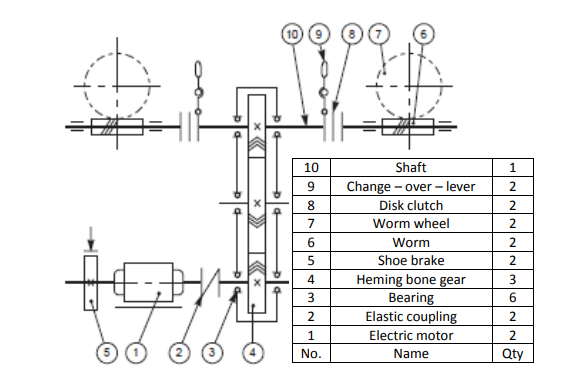
Assembly drawings show the entire device or system, as well as the placement and identification of each component. The roles of an assembly drawing include component identification, assembly order labeling, and occasionally even standard requirements. These drawings additionally include orthogonal plans, sections, elevations, weight, mass, a bill of materials (BOM), and other details. These drawings act as a common pictorial language for two technical people, allowing them to communicate.
Assembly drawings is For?
Assembly drawings are created for things, units, machines, and assemblies. They can also assist with mechanical drafting services, whether it’s putting together a simple kit, like furniture, or a sophisticated component of a mechanism. The following three specifications should be met by an assembly drawing:
Maintenance requirement
Operational requirement
Manufacturing requirements
Assembly drawings’ significance
Any mechanism that is produced in bulk requires many precisely constructed assemblies and sub-assemblies. Without assembly drawings, technical information would need to be conveyed orally or in writing rather than graphically, which would lead to costly misunderstandings, errors, and lost time. Producing automobiles, aircraft, and other constructions that could potentially save lives has relied heavily on the efficient use of assembly drawings.
Assembly drawings typically provide the following information, which is sufficient to enable the assembly of a component:
Several components or supporting assemblies.
Enough orthogonal views that clearly demonstrate how the components work together.
Section views display details and demonstrate how pieces go together.
Only the overall size of the assembly or the machining processes required for assembly are indicated by dimensions on assembly drawings.
Process requirements, protective coatings, and other pertinent information for assembling the item.
A components list or bill of materials with a unique identifier for each item that will be used in the assembly.
Information on the revision or issue
Types of assembly drawings
Assembly drawings are often categorized into the following five groups according to use:
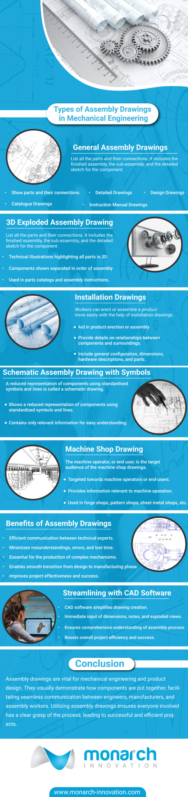
General Assembly Drawings
General assembly drawings list all the parts and their connections. It includes the finished assembly, the sub-assembly, and the detailed sketch for the component. Four categories can be used to classify the drawing:
Sample of a general assembly drawing Image credit:- https://www.cadcrowd.com/
Design Drawings: Design drawings are created during the design phase and show various constructions, steel structures, and machinery that need to be put together from various angles. It helps in understanding how the object functions, including its shape and the clearances between different pieces.
Detailed Drawings: Detailed assembly drawings contain information about the materials, dimensions, joining techniques, etc., and show how the components fit together. It is possible to create magnified views of certain pieces and how they will fit together in addition to the standard assembly drawings. Sub-assemblies and individual parts are used to construct some types of machinery and buildings. Before being used in their final assembly, they can be put together and tested as a unit.
Assembly Drawings for catalogues: Unique assembly drawings made specifically for company catalogues are known as assembly drawings for catalogues. These designs simply display the crucial information and measurements that a potential customer would find interesting.
Assembly Drawings for instruction manuals: Every time a finished machine needs to be taken apart for shipping, reassembled, and installed at its location, assembly drawings for instruction manuals are required. To facilitate the reassembly process, each component in these drawings has a number.
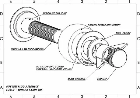
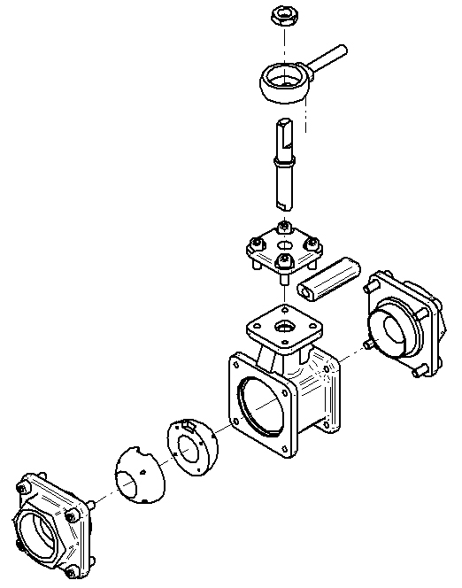
Exploded assembly drawing.
These are technical illustrations of an object that highlight all its parts. The 3D exploded diagrams produced by Assembly Modelling Services depict the components slightly separated or hanging in surrounding space in order of assembly. This provides a general sense of how the finished item will come together. These drawings are used in parts catalogues, assembly instructions, manuals, and other instructional materials because they are easy to grasp even for laypeople.
Example of exploded assembly drawing. Image credit: https://www.designingbuildings.co.uk/wiki/
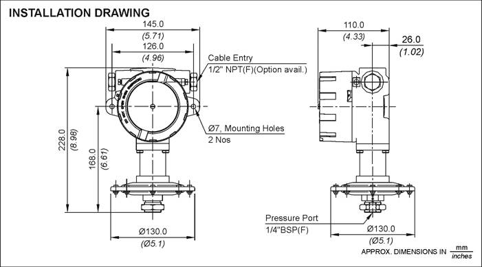
Installation drawings
Workers can erect or assemble a product more easily with the help of installation drawings. They provide details on the relationship between a component and its supporting or surrounding factors. Additionally, it will display a general configuration, dimensional data, hardware descriptions, and parts.
Example of installation drawing. Image credit: https://www.designingbuildings.co.uk/wiki/
Schematic Assembly Drawing
A reduced representation of components using standardized symbols and lines is called a schematic drawing. Only relevant information is shown in schematic diagrams.
The machine operator, or end user, is the target audience of the machine shop drawings. Since the dimensions and information relevant to the earlier steps are not important to the machinist, just the information pertaining to the machine’s operation is provided. Drawings from forge shops, pattern shops, sheet metal shops, etc. all operate on the same principle.
In conclusion, assembly drawings are vital for mechanical engineering and product design because they show how different parts and components are put together visually. Professionals may effectively explain the complexities of product assembly to engineers, manufacturers, and assembly workers by using a drawing sheet and assembly file, providing a smooth transfer from the design phase to the manufacturing phase. All parties engaged in the assembly process will have a clear grasp of the procedure with a well-prepared assembly drawing that includes dimensions and annotations added to the design sheet. The inclusion of dimensions, tolerances, and other pertinent data not only lowers the possibility of mistakes occurring during the assembly process but also improves the project’s overall effectiveness and success.
The process of producing new drawings from an existing assembly file is greatly streamlined by the usage of CAD software while developing assembly drawings. The software enables the immediate input of dimensions, notes, and exploded views to the drawing sheet, resulting in a thorough comprehension of the assembly procedure. By ensuring that everyone involved has a comprehensive grasp of the assembly process from the individual components to the finished system or product, these drawings eventually improve the project’s overall success and efficiency.
Ready to make your project a success with assembly drawing services? Contact us now!
FAQs
What is an assembly drawing?
An assembly drawing is a technical drawing that shows how different parts and components fit together to create a larger product or structure. It provides a visual representation of the assembly process and helps in understanding the relationships between the various parts. Assembly drawings are commonly used in engineering, manufacturing, and construction industries.
What are the different types of assembly drawings?
There are several types of assembly drawings, including exploded view drawings, detailed assembly drawings, and schematic assembly drawings. Each type serves a specific purpose and provides different levels of detail and information about the assembly.
What is the purpose of an assembly drawing?
The purpose of an assembly drawing is to show how different parts of a machine fit together and to help engineers and technicians understand how to assemble the machine.
What software is used to create assembly drawings?
Some popular software used for creating assembly drawings include AutoCAD, SolidWorks, CATIA, Siemens NX, and PTC Creo. These software programs offer a range of features and capabilities to create detailed and accurate assembly drawings.
The world of computer-aided design (CAD) technology is constantly evolving, introducing innovative trends that shape the way we design and create. In this captivating blog series, we delve into the latest advancements in CAD including efficient CAD conversion methods, exploring the cutting-edge innovations that are propelling the industry forward. From software developments to hardware breakthroughs, we uncover the key elements that are reshaping the CAD landscape. Discover the power of parametric modeling, enabling dynamic and intelligent design iterations. Explore the realm of generative design, where algorithms and artificial intelligence drive creative exploration and optimization.
Witness the transformative impact of simulation and analysis capabilities, reducing reliance on physical prototypes. Immerse yourself in the world of virtual reality integration, revolutionizing design visualization and interaction. Experience the seamless collaboration facilitated by cloud-based CAD solutions, enhancing teamwork and project outcomes. Through real-world industry applications, such as automotive, aerospace, architecture, and consumer products, witness how CAD technology drives innovation and transforms sectors. Join us on this exhilarating journey as we unveil the latest trends and innovations in CAD technology, inspiring you to embrace the possibilities and shape the future of design.
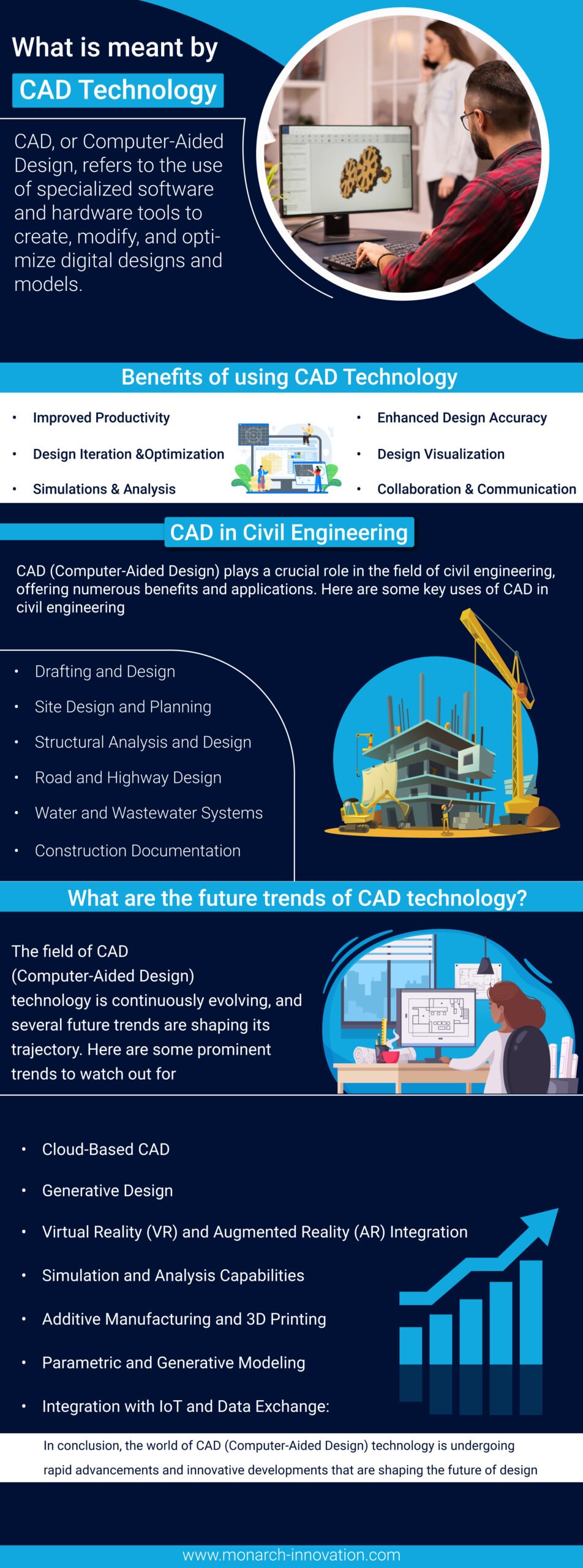
What is meant by CAD Technology?
CAD, or Computer-Aided Design, refers to the use of specialized software and hardware tools to create, modify, and optimize digital designs and models. It is a technology that enables designers, engineers, and architects to design and visualize objects, structures, or systems in a virtual environment. CAD technology provides a wide range of capabilities, including 2D drafting, 3D modeling, parametric modeling, simulation, analysis, and documentation.
By leveraging CAD software, professionals can streamline the design process, improve accuracy, and enhance productivity. CAD technology has transformed industries such as engineering, architecture, manufacturing, and product design by enabling faster design iterations, precise measurements, efficient collaboration, and the ability to simulate real-world conditions. It has become an essential tool for creating and communicating complex designs, facilitating innovation, and bringing ideas to life in a digital realm.
Benefits of using CAD Technology
The use of CAD (Computer-Aided Design) technology offers numerous benefits across various industries and disciplines. Here are some of the key advantages:
Improved Productivity: CAD tools provide efficient workflows, automation, and a wide range of design features that significantly increase productivity. Designers can create and modify designs more quickly and accurately compared to traditional manual methods, saving time and effort.
Enhanced Design Accuracy: CAD technology enables precise and accurate design creation. Measurements, dimensions, and geometric relationships can be precisely defined and maintained, reducing errors, and ensuring design integrity.
Design Visualization: CAD software allows designers to visualize their designs in 2D or 3D, providing a realistic representation of the final product or structure. This visualization aids in design analysis, evaluation, and communication with stakeholders, leading to better decision-making.
Design Iteration and Optimization: CAD tools enable designers to easily iterate and refine designs. Changes can be made swiftly, and multiple design options can be explored, facilitating optimization and innovation. This iterative process helps to create more efficient and effective designs.
Simulations and Analysis: CAD technology often includes simulation and analysis capabilities that allow designers to test and evaluate their designs virtually. These simulations can assess factors such as structural integrity, fluid dynamics, heat transfer, and more. By identifying and addressing design issues early in the process, costly physical prototyping and testing can be minimized.
Collaboration and Communication: CAD software facilitates effective collaboration among team members, allowing them to work on the same design simultaneously and share design data seamlessly. This improves communication, reduces errors, and enhances coordination throughout the design process.
Documentation and Manufacturing: CAD tools generate accurate and comprehensive design documentation, including drawings, specifications, and bills of materials. This information can be easily shared with manufacturers, ensuring precise replication of the design and minimizing production errors.
Design Reusability and Maintenance: CAD technology enables the creation of design libraries and parametric models, making it easier to reuse and modify existing designs. This feature accelerates design iterations, simplifies maintenance, and promotes design standardization.
Cost and Time Savings: By streamlining the design process, reducing errors, and enabling virtual testing, CAD technology helps to save costs and time associated with manual drafting, physical prototyping, and rework. It promotes efficiency and can expedite time-to-market for products.
Cad in civil engineering
CAD (Computer-Aided Design) plays a crucial role in the field of civil engineering, offering numerous benefits and applications. Here are some key uses of CAD in civil engineering:
Drafting and Design: CAD software allows civil engineers to create accurate 2D and 3D drawings of structures, such as buildings, bridges, roads, and dams. It enables precise detailing of architectural elements, structural components, and infrastructure layouts.
Site Design and Planning: CAD tools assist in site design and planning by providing tools for survey data integration, contour modeling, and land development. Civil engineers can create digital terrain models, analyze site conditions, and design grading plans more efficiently.
Structural Analysis and Design: CAD software incorporates structural analysis capabilities that enable engineers to evaluate the strength, stability, and performance of buildings and infrastructure. It aids in designing structural elements, such as beams, columns, and foundations, while ensuring compliance with safety standards and regulations.
Road and Highway Design: CAD technology facilitates the design of roads, highways, and transportation networks. Engineers can create alignments, cross-sections, and profiles, optimize road geometry, and analyze factors like traffic flow and safety.
Water and Wastewater Systems: CAD tools assist in the design and modeling of water supply, drainage, and wastewater systems. Engineers can create pipe networks, hydraulic profiles, and stormwater management plans, ensuring efficient and sustainable water infrastructure.
Construction Documentation: CAD software allows civil engineers to generate construction drawings, specifications, and quantity takeoffs. This documentation provides precise instructions for contractors, reducing errors during construction and enhancing project coordination.
Visualization and Presentations: CAD technology enables realistic 3D visualizations and renderings of civil engineering projects. Engineers can create walkthroughs, flyovers, and virtual reality experiences to effectively communicate design concepts to clients, stakeholders, and regulatory bodies.
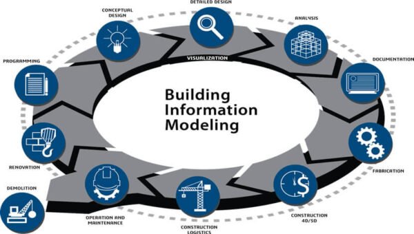
BIM Integration: Building Information Modeling (BIM) is closely linked to CAD in civil engineering. BIM software utilizes CAD data to create intelligent, information-rich models that facilitate collaboration and coordination among different disciplines involved in a project, including architects, structural bim engineers, and MEP (Mechanical, Electrical, Plumbing) professionals.
Project Collaboration and Management: CAD tools support collaborative work environments, allowing civil engineering teams to work concurrently on different aspects of a project. It promotes efficient communication, reduces conflicts, and streamlines project management processes.
CAD has transformed the civil engineering industry by providing powerful tools for design, analysis, documentation, and collaboration. It enhances efficiency, accuracy, and productivity while facilitating innovation in infrastructure development and construction projects.
What are the future trends of CAD technology?
The field of CAD (Computer-Aided Design) technology is continuously evolving, and several future trends are shaping its trajectory. Here are some prominent trends to watch out for:
Cloud-Based CAD: Cloud computing is revolutionizing CAD, allowing users to access software and store data in the cloud. This trend enables real-time collaboration, seamless data sharing, and enhanced flexibility across multiple devices and locations.
Generative Design: Generative design takes advantage of algorithms and artificial intelligence to explore numerous design iterations and find optimal solutions based on specified constraints. It enables designers to harness the power of computational algorithms to generate innovative and efficient designs.
Virtual Reality (VR) and Augmented Reality (AR) Integration: CAD systems are increasingly incorporating AR and VR technologies, providing immersive experiences for design visualization and interaction. Designers can step into virtual environments, visualize their designs at scale, and make real-time modifications, enhancing the design review and validation process.
Simulation and Analysis Capabilities: CAD tools are becoming more advanced in terms of simulation and analysis features. Integrated analysis modules allow engineers to perform virtual testing, predict performance under different conditions, and optimize designs early in the development process, reducing the need for physical prototypes.
Additive Manufacturing and 3D Printing: CAD technology is closely intertwined with additive manufacturing and 3D printing processes. As these manufacturing methods continue to advance, CAD systems will incorporate specific tools and workflows for designing complex geometries and optimizing designs for additive manufacturing.
Parametric and Generative Modeling: Parametric modeling, which allows the use of variables and relationships to create intelligent designs, will continue to evolve. Additionally, generative modeling, driven by AI algorithms, will offer designers new ways to explore and generate design options based on specific objectives and constraints.
Integration with IoT and Data Exchange: CAD technology is expected to integrate more closely with the Internet of Things (IoT) systems and enable seamless data exchange between physical devices and digital models. This integration will streamline design processes, allow for real-time data-driven decisions, and facilitate the development of smart connected products and infrastructure.
Artificial Intelligence and Machine Learning: AI and machine learning techniques will further enhance CAD capabilities, including automating repetitive design tasks, predicting design performance, and providing intelligent design recommendations based on historical data and user preferences.
Enhanced User Experience: CAD software interfaces and workflows will continue to evolve, focusing on user-friendliness, intuitive design, and enhanced productivity. User-centric features such as gesture-based controls, natural language processing, and context-aware design tools will contribute to a more efficient and enjoyable CAD experience.
These trends reflect the ongoing advancements in CAD technology, driven by the demand for increased productivity, design innovation, collaboration, and the integration of emerging technologies. By staying abreast of these trends, professionals in the field can adapt and leverage the latest tools and capabilities to enhance their design workflows and stay at the forefront of the industry.
Conclusion
In conclusion, the world of CAD (Computer-Aided Design) technology is undergoing rapid advancements and innovative developments that are shaping the future of design. The trends discussed in this blog highlight the ongoing transformation and the immense potential of CAD in various industries. Embracing these trends and staying abreast of the latest developments will be crucial for individuals and organizations to thrive in this dynamic and ever-evolving landscape of CAD technology. ContactMonarch Innovative to use CAD Technology effectively!
When it comes to interior design and construction, two terms that often come up are “millwork” and “casework.” While these terms may sound similar, they refer to distinct elements that play crucial roles in creating functional and aesthetically pleasing spaces. Understanding the key differences between millwork and casework is essential for anyone involved in the design or renovation process. In this blog post, we will delve into the nuances of Millwork construction and casework, exploring their definitions, purposes, and how they contribute to the overall look and feel of a space. Whether you’re a homeowner, architect, or design enthusiast, this guide will help you confidently navigate these concepts.
What is Millwork?
Millwork refers to the customized wooden architectural elements and finished carpentry found in interior spaces. It involves the precise crafting and installation of various woodwork components, such as moldings, trim, doors, cabinetry, and built-in furniture. Millwork is typically created by skilled artisans who use specialized tools and techniques to shape and manipulate wood into intricate designs. These crafted pieces are then installed in residential, commercial, and institutional settings to add both functionality and aesthetic appeal to the space. Millwork or millwork construction plays a significant role in enhancing the overall architectural style, character, and visual impact of a room, creating a sense of craftsmanship and refinement.
What is Casework?
Casework refers to installing pre-built cabinets, shelves, and storage units in interior spaces. Unlike millwork, which involves custom woodworking, casework involves the use of standardized modular components that are manufactured off-site and then assembled on-site. Casework offers versatility and efficiency, allowing for quick installation and customization options. It is commonly used in residential, commercial, and institutional settings to provide functional storage solutions and organization. From kitchen cabinets and bathroom vanities to office storage systems and retail display units, casework construction offers a wide range of design possibilities to optimize space utilization while maintaining a sleek and streamlined aesthetic.
Benefits: Millwork vs Casework
The choice between millwork and casework depends on the specific project requirements, budget, desired aesthetic, and timeline. Both options offer unique benefits that can enhance interior spaces in different ways.
Millwork Benefits:
Customization: Millwork allows for limitless customization options, as each piece is crafted according to specific millwork design requirements. Architectural millwork ensures a perfect fit and unique aesthetic appeal.
Architectural Character: Millwork adds architectural character and visual interest to interior spaces, creating a sense of craftsmanship and elegance.
Quality Craftsmanship: Millwork construction is often created by skilled artisans who pay meticulous attention to detail, resulting in high-quality and durable woodwork.
Flexibility: Millwork or Architectural millwork can be adapted to suit various architectural styles and several millwork design concepts, offering versatility in creating cohesive and personalized interiors.
Casework Benefits:
Efficiency: Casework is prefabricated off-site, allowing for faster installation and reduced construction time compared to custom millwork.
Cost-Effective: Casework is typically less expensive than millwork since it utilizes standardized modular components, making it a budget-friendly option.
Consistency: Casework ensures consistent quality and dimensions since it is manufactured using precise production methods and machinery.
Versatility: Casework construction offers a wide range of storage and organizational solutions, making it ideal for both residential and commercial applications where functionality is key.
Application: Millwork v/s Casework
Discover the diverse uses of millwork and casework construction, and how they enhance the functionality and aesthetics of interior spaces in distinct yet complementary ways.
Millwork Applications:
Millwork design is often employed to create intricate moldings, such as crown moldings, baseboards, and chair rails. These elements add a touch of elegance and sophistication to walls and ceilings. Millwork construction is ideal for crafting custom cabinetry and built-in storage solutions. From kitchen cabinets and bathroom vanities to bookshelves and entertainment centers, architectural millwork enhances functionality while providing a seamless and stylish integration with the overall design. Architectural millwork extends to the creation of custom doors and windows. These meticulously crafted elements not only serve their functional purposes but also contribute to the overall aesthetic appeal of a space. Also, these can be utilized to design and construct paneling and wainscoting, adding texture, depth, and visual interest to walls.
Casework Applications:
Casework construction finds widespread use in commercial spaces such as offices, retail stores, and hospitality venues. It involves the installation of modular cabinetry, display cases, and storage units to optimize organization and functionality. Casework is commonly employed in educational institutions to provide storage solutions in classrooms, laboratories, and libraries. It offers durability and flexibility, allowing for easy reconfiguration as per changing needs. Casework is used extensively in healthcare facilities for storage, shelving, and built-in cabinetry solutions in patient rooms, laboratories, and administrative areas. Casework construction also offers practical storage solutions in residential settings, including closets, laundry rooms, and garages. Modular cabinets and shelves provide organization and maximize space utilization.
Costing: Millwork vs. Casework – Comparing Financial Considerations
When it comes to cost, there are significant differences between millwork and casework in interior design projects. Millwork, being custom-made, tends to have a higher price tag due to the craftsmanship and customization involved. The materials, intricate detailing, and skilled labor contribute to Millwork construction’s elevated cost. On the other hand, casework offers a more budget-friendly option as it utilizes standardized modular components, reducing manufacturing and installation expenses. Casework’s cost-effective nature makes it a popular choice for projects with limited budgets or when time constraints are a factor. Ultimately, the decision between millwork and casework relies on the project’s financial resources and the desired level of customization and quality.
Which is preferable? Millwork v/s Casework
The preference between millwork and casework ultimately depends on the specific needs and priorities of a project. Millwork is favored when customization, craftsmanship, and a high-end aesthetic are of utmost importance. It offers limitless design possibilities, architectural character, and an unparalleled level of attention to detail. On the other hand, casework is preferred for its cost-effectiveness, efficiency, and versatility. It provides standardized storage solutions, and quick installation, and is well-suited for projects with limited budgets or tight timelines. Ultimately, the choice between Architectural millwork and casework is subjective and should be based on the project’s requirements, design vision, budget, and desired level of customization.
In conclusion,
Both millwork and casework have their unique advantages in interior design. Millwork offers custom craftsmanship and exquisite detailing, while casework provides cost-effective modular solutions. The decision between the two depends on factors such as budget, timeline, and desired level of customization. Ultimately, it’s about finding the right balance between aesthetic appeal, functionality, and financial considerations to create stunning and functional spaces.
BIM has revolutionized the construction industry, offering a holistic approach to project management. In this article, we delve into the captivating realms of 3D, 4D, 5D, 6D, and 7D BIM. With BIM dimensions, architects, engineers, and contractors can unlock unparalleled insights and efficiencies throughout the entire project lifecycle.
As a project progresses through different phases, the level of development in a BIM model also increases to different levels, including LOD 100, 200, 300, 350, 400, and 500. LOD is an industry-standard that defines various development stages of construction projects in BIM.
In this blog, we will explore the fascinating world of Building Information Modeling (BIM) and its dimensions! Join us as we unravel the innovative potential of BIM services, harnessing the power of virtual models, scheduling integration, cost estimation, sustainability analysis, and facility management. Discover how each dimension elevates project coordination and amplifies success. Get ready to embark on a remarkable journey through the multidimensional landscape of BIM!
What is meant by BIM?
BIM, short for Building Information Modeling, is a digital process that allows the creation and management of comprehensive 3D models of buildings and infrastructure projects. These models, known as BIM models, are rich in data and provide a collaborative platform for architects, engineers, contractors, and other stakeholders to work together effectively.
BIM dimensions refer to different aspects or levels of information that can be incorporated into the BIM models. Each dimension represents a specific type of data that enhances project management and decision-making throughout the project lifecycle. The types of BIM dimensions are:
3D BIM: Represents the spatial representation of the physical elements of a building or infrastructure project.
4D BIM: Adds the dimension of time to the 3D model, incorporating scheduling and sequencing information.
5D BIM: Combines the 3D model with cost data, allowing for accurate cost estimation and budgeting.
6D BIM: Includes sustainability and energy analysis, enabling the evaluation of environmental performance.
7D BIM: Integrates facility management information, such as operation and maintenance manuals, warranties, and asset management data.
By incorporating these BIM dimensions into projects, BIM services can greatly enhance collaboration, efficiency, and decision-making throughout the entire lifecycle of a building or infrastructure project.
Unleashing the Power of BIM Services: Transforming Construction through Enhanced Collaboration and Efficiency
In the fast-paced world of construction, embracing Building Information Modeling (BIM) services has become paramount for success. BIM services offer a comprehensive suite of tools and techniques that revolutionize project management, design, and coordination. By harnessing the power of BIM dimensions, architects, engineers, contractors, and stakeholders can unlock a multitude of benefits throughout the project lifecycle.
3D Modeling and Visualization: BIM services provide sophisticated 3D modeling capabilities, enabling stakeholders to visualize the project in a virtual environment. This enhances design exploration, clash detection, and spatial coordination, resulting in reduced errors and rework.
Clash Detection and Coordination: With BIM services, clashes between different building components can be identified and resolved early in the design phase. This streamlines the construction process, minimizes delays, and improves overall project coordination.
Quantity Take-off and Estimation: BIM services enable accurate quantity take-off and cost estimation. By integrating 3D models with cost data, stakeholders can generate detailed quantity reports and make informed decisions regarding project budgets and resource allocation.
Construction Sequencing (4D BIM): BIM services incorporate the dimension of time, allowing for 4D visualization and construction sequencing. This facilitates effective project scheduling, resource allocation, and project phasing, ensuring efficient project execution.
Sustainability and Energy Analysis (5D BIM): BIM services include sustainability analysis tools that assess the environmental impact and energy performance of a building. This empowers stakeholders to make informed decisions regarding materials, systems, and energy-efficient strategies.
Facility Management Integration (7D BIM): BIM services extend beyond construction and into the operational phase of a building. Facility management integration enables the seamless transfer of asset data, maintenance schedules, and warranties, supporting efficient facility management and maintenance.
By embracing BIM services, the construction industry can embrace enhanced collaboration, streamlined workflows, and improved project outcomes. The integration of BIM dimensions empowers stakeholders to make data-driven decisions, reduce costs, minimize errors, and deliver projects with unmatched efficiency and sustainability. The future of construction lies in the transformative potential of BIM services, where virtual models seamlessly bridge the gap between concept and reality.
Breaking Ground with 3D BIM: Unveiling the Third Dimension of Construction Excellence
3D BIM, the third dimension of Building Information Modeling (BIM), revolutionizes the construction industry by providing a spatial representation of building elements in a virtual environment. It encompasses the creation of accurate and detailed 3D models that serve as a foundation for enhanced collaboration, visualization, and coordination among project stakeholders.
The benefits of 3D BIM are profound and extend across the entire project lifecycle:
Enhanced Visualization: 3D BIM allows stakeholders to visualize the project in a virtual space, providing a realistic representation of the building’s form, structure, and spatial relationships. This visual clarity fosters better communication, improved design exploration, and informed decision-making.
Clash Detection and Coordination: With 3D BIM, clashes and conflicts between different building elements can be identified and resolved before construction begins. This early clash detection minimizes costly on-site conflicts, reduces rework, and improves overall project coordination.
Improved Design Communication: 3D BIM models serve as powerful communication tools, enabling stakeholders to easily convey design intent and concepts to clients, contractors, and regulatory authorities. This facilitates a shared understanding of the project, leading to fewer misunderstandings and improved project outcomes.
Efficient Space Utilization:3D BIM models allow for optimized space planning and utilization. Designers can explore different spatial arrangements, evaluate functionality, and make informed decisions regarding spatial requirements, circulation paths, and room layouts, resulting in efficient and functional building designs.
Accurate Quantity Take-off: 3D BIM models provide the foundation for accurate quantity take-off, enabling stakeholders to generate detailed material and quantity reports. This streamlines the estimation process, improves cost control, and supports effective procurement and resource allocation.
Improved Stakeholder Collaboration: 3D BIM fosters collaboration among project stakeholders by providing a centralized and accessible platform for sharing information, design changes, and project updates. This promotes transparency, reduces coordination errors, and enhances teamwork throughout the project lifecycle.
With the advent of 3D BIM, the construction industry has witnessed a paradigm shift towards more efficient, accurate, and collaborative project delivery. By embracing the third dimension of BIM, stakeholders can navigate the complexities of construction with ease, visualize designs in unprecedented detail, and lay the groundwork for successful project outcomes. The future of BIM in construction lies in the immersive power of 3D BIM, where virtual models bring projects to life and pave the way for construction excellence.
Empowering Construction Schedules with 4D BIM: Unleashing the Fourth Dimension of Project Success
4D BIM, also known as the fourth dimension of Building Information Modeling (BIM), introduces the element of time into the digital modeling process. It combines the spatial representation of 3D BIM with the scheduling and sequencing information of construction activities. By incorporating the fourth dimension, 4D BIM revolutionizes project management and brings a multitude of benefits to construction projects.
The benefits of 4D BIM are significant and impact various aspects of the project lifecycle:
Visualizing Construction Sequences: 4D BIM enables stakeholders to visualize the construction sequence in a dynamic and interactive manner. This visual representation of activities and their dependencies allows for a clear understanding of the project timeline, aiding in project planning and coordination.
Optimized Construction Schedules: With 4D BIM, project schedules can be accurately integrated into the model. This integration facilitates the identification of potential clashes or delays, enabling stakeholders to make informed decisions and optimize the construction schedule for improved efficiency and productivity.
Early Clash Detection and Conflict Resolution: By overlaying construction sequences onto the 3D model, 4D BIM helps identify clashes and conflicts between different activities, trades, or resources. Early clash detection allows for proactive conflict resolution, reducing costly on-site rework and delays.
Resource and Equipment Management: 4D BIM provides a comprehensive overview of resource allocation, enabling stakeholders to effectively manage equipment, materials, and labour throughout the construction process. This improves resource utilization, minimizes downtime, and enhances productivity.
Communication and Stakeholder Engagement: The visual representation of construction sequences in 4D BIM facilitates effective communication and stakeholder engagement. It helps convey the project timeline, milestones, and progress to clients, contractors, and project teams, fostering collaboration and understanding.
Improved Project Control and Decision-making: 4D BIM enhances project control by allowing stakeholders to monitor project progress, identify potential delays, and analyze the impact of schedule changes. This empowers informed decision-making, enabling proactive measures to mitigate risks and ensure project success.
With the integration of the fourth dimension, 4D BIM brings a new level of insight and control to construction projects. It enhances visualization, streamlines scheduling, improves coordination, and empowers stakeholders to make informed decisions throughout the project lifecycle. By embracing 4D BIM, the construction industry is propelled into a new era of efficient and effective project management, where time becomes an integral component of digital modeling and construction success.
Unleashing Cost Efficiency with 5D BIM: Expanding the Boundaries of Project Estimation and Control
5D BIM, the fifth dimension of Building Information Modeling (BIM), introduces the element of cost into the digital modeling process. By integrating cost data with the spatial and temporal aspects of 3D and 4D BIM, 5D BIM enables accurate cost estimation, budgeting, and control throughout the entire project lifecycle. This innovative approach brings a multitude of benefits to construction projects.
The benefits of 5D BIM are transformative, impacting project management and cost control:
Accurate Cost Estimation:5D BIM allows stakeholders to generate accurate cost estimates by associating cost data with individual components within the 3D model. This level of detail improves cost accuracy, mitigates budget overruns, and facilitates informed decision-making.
Real-Time Cost Analysis: With 5D BIM, project stakeholders can perform real-time cost analysis throughout the project lifecycle. This empowers them to evaluate the cost impact of design changes, material substitutions, and scheduling adjustments, enabling proactive cost control and risk management.
Quantity Take-off Optimization: 5D BIM streamlines the process of quantity take-off by automating the extraction of quantities from the 3D model. This reduces manual effort, minimizes errors, and expedites the estimation process, leading to increased efficiency and productivity.
Improved Cost Control and Reporting: The integration of cost data within the BIM model facilitates continuous cost monitoring and control. It enables stakeholders to track actual costs against budgets, generate accurate reports, and make timely adjustments to ensure project financial success.
Enhanced Value Engineering: 5D BIM facilitates value engineering by providing insights into cost implications during the design phase. This enables stakeholders to explore cost-saving alternatives, optimize material usage, and identify opportunities for value enhancement, resulting in cost-effective and sustainable designs.
Stakeholder Collaboration and Transparency: 5D BIM promotes collaboration and transparency among project stakeholders. By visualizing cost data within the model, it fosters a shared understanding of project finances, aligns expectations, and enables better collaboration between owners, designers, contractors, and cost consultants.
With the integration of cost data, 5D BIM empowers stakeholders to make informed decisions, enhance cost control, and maximize project value. It revolutionizes the estimation process, improves cost visibility, and supports efficient budget management throughout the project lifecycle. By embracing 5D BIM, the construction industry can embark on a new era of cost efficiency, where accurate cost estimation and control become integral components of digital modeling and project success.
Revolutionizing Construction Management: Unleashing the Power of 6D BIM.
In the realm of construction management, the advent of Building Information Modeling (BIM) has transformed the way projects are planned, designed, and executed. One notable advancement in this field is the emergence of 6D BIM, an innovative approach that goes beyond traditional 3D modeling and incorporates the dimension of time and cost. By integrating project scheduling and cost data with the digital model, 6D BIM revolutionizes construction management, offering a comprehensive and dynamic platform for enhanced decision-making and project control.
Benefits of 6D BIM:
Enhanced Project Visualization: 6D BIM provides a comprehensive digital representation of the project, allowing stakeholders to visualize the entire lifecycle of the construction project. This includes construction sequencing, maintenance activities, and future renovations, facilitating better understanding and collaboration among team members.
Improved Time and Cost Management: By incorporating scheduling and cost data, 6D BIM enables accurate estimation and forecasting throughout the project lifecycle. This helps identify potential issues, optimize resource allocation, and enhance project planning, ultimately leading to improved time and cost management.
Enhanced Sustainability and Energy Efficiency: 6D BIM empowers project teams to assess the environmental impact and energy performance of a building throughout its lifecycle. By simulating and analyzing energy consumption, carbon emissions, and operational costs, stakeholders can make informed decisions to optimize sustainability and energy efficiency, ensuring long-term environmental benefits.
Streamlined Facility Management: With 6D BIM, facility managers can access a wealth of information about the building, including maintenance schedules, equipment specifications, and operating manuals. This centralized database streamlines facility management tasks, reducing maintenance costs, improving operational efficiency, and extending the lifespan of the asset.
Mitigated Risks and Enhanced Safety: 6D BIM allows for virtual simulations and clash detections, enabling the identification and resolution of potential clashes and conflicts before construction begins. This minimizes on-site risks, improves safety, and helps avoid costly rework, thereby enhancing overall project quality.
Transforming Construction Management: Unleashing the Potential of 7D BIM
Building Information Modeling (BIM) has revolutionized the construction industry, providing an advanced platform for design, planning, and project execution. Taking the capabilities of BIM even further, 7D BIM encompasses the dimensions of time, cost, and facility management. By integrating operational and maintenance data into the digital model, 7D BIM offers a comprehensive and dynamic approach to construction management, enabling improved decision-making, efficiency, and long-term value.
Benefits of 7D BIM:
Efficient Facility Operations and Maintenance: 7D BIM integrates comprehensive facility management data into the digital model, including equipment specifications, maintenance schedules, and asset lifecycle information. This enables facility managers to streamline operations, plan maintenance tasks, and optimize resource allocation, resulting in reduced downtime, enhanced performance, and cost savings.
Lifecycle Cost Analysis: By incorporating cost data throughout the entire lifecycle of a project, 7D BIM enables accurate cost estimation, forecasting, and analysis. Stakeholders can assess the financial implications of design decisions, material choices, and maintenance strategies, leading to improved cost control and budget management.
Improved Asset Performance and Longevity: With 7D BIM, project teams can monitor and analyze the performance of building systems and components throughout their operational lifespan. This allows for proactive maintenance, early detection of issues, and the optimization of asset performance, resulting in extended asset longevity and enhanced value.
Enhanced Sustainability and Energy Efficiency: 7D BIM empowers stakeholders to analyze and optimize the environmental impact and energy efficiency of a building over its lifecycle. By simulating energy consumption, conducting energy audits, and exploring sustainable design options, teams can make data-driven decisions that reduce carbon emissions, lower operational costs, and promote sustainable practices.
Seamless Collaboration and Communication: 7D BIM provides a central platform for collaboration among project stakeholders, facilitating effective communication and information exchange. Real-time access to accurate and up-to-date project information ensures transparency, minimizes errors, and improves coordination, leading to smoother project workflows and reduced rework.
The emergence of 7D BIM has elevated construction management to new heights by incorporating time, cost, and facility management dimensions into the digital model. The benefits of 7D BIM, including efficient facility operations, lifecycle cost analysis, improved asset performance, sustainability enhancements, and seamless collaboration, empower construction professionals to make informed decisions, optimize resources, and deliver projects with greater efficiency and long-term value. By embracing the power of 7D BIM, the construction industry can pave the way for more sustainable, cost-effective, and successful projects in the future.
Conclusion
In the realm of construction and design, the evolution of Building Information Modeling (BIM) has introduced a new dimension to project management. From the foundational 3D BIM, which provides visual representations, to the advanced 7D BIM, incorporating time, cost, and facility management, each dimension adds value and efficiency to the process. The utilization of BIM dimensions, such as 4D for project scheduling and 6D for environmental analysis, has revolutionized the industry.
Monarch Innovation, with its expertise in BIM services, is at the forefront of this innovation, empowering construction professionals to unlock new levels of collaboration, decision-making, and project control. Embracing BIM dimensions is the key to a more streamlined, sustainable, and successful future in construction. Contact us for all your BIM Services requirements, we are happy to help.
In product development, two different approaches are commonly used: forward engineering and reverse engineering. While forward engineering involves creating new products from scratch, reverse engineering involves analyzing and replicating existing products. This blog will explore the key differences between forward engineering and reverse engineering, and the various applications of both approaches.
Forward engineering and reverse engineering are two different approaches used in product development. While forward engineering involves creating new products from scratch, reverse engineering involves analyzing and replicating existing products. Each approach has its advantages and disadvantages, and the decision to use one or the other depends on the specific needs of a project. Now, we will explore the key differences between forward engineering and reverse engineering in more detail.
Forward Engineering
Forward engineering is the traditional approach to product development, in which designers and engineers start with a concept or idea and work through a series of steps to create a final product. This process typically involves several stages, including ideation, prototyping, testing, and refinement. In forward engineering, the design and development process starts with a clear understanding of the requirements and specifications of the product. Designers and engineers then work together to develop a detailed plan for the product, which includes defining the materials, manufacturing processes, and assembly procedures that will be used.
Once the plan is in place, the product is then prototyped and tested to ensure that it meets all the necessary requirements. Feedback from testing is used to refine the design and improve the product until it is ready for production. Forward engineering is commonly used in product development for a wide range of industries, including manufacturing, electronics, and software. The key advantage of forward engineering is that it allows designers and engineers to create products that are customized to meet specific requirements and to optimize the design for the intended purpose.
Reverse Engineering
Reverse engineering, on the other hand, involves the analysis and replication of existing products. This process is often used when there is a need to reproduce a product that is no longer available or to modify an existing product to improve its performance. Reverse engineering typically involves several stages, including disassembly, measurement, analysis, and replication. The first step in reverse engineering is to disassemble the product and analyze its components to understand how it was designed and manufactured.
Once the product has been disassembled, measurements are taken of each component and its relationship to other parts of the product. This information is then used to create a 3D model of the product, which can be used to create new designs or modify the existing product. Reverse engineering is commonly used in industries such as aerospace, automotive, and manufacturing. The key advantage of reverse engineering is that it allows designers and engineers to understand the intricacies of an existing product and to make improvements or modifications based on that knowledge.
Comparison
The main difference between forward engineering and reverse engineering is the starting point of the design process. In forward engineering, the design process starts with a concept or idea and moves towards a finished product, while in reverse engineering, the process starts with a finished product and moves towards a new design.
Another key difference between forward engineering and reverse engineering is the level of control that designers and engineers have over the design process. In forward engineering, designers and engineers have complete control over the design and development of the product, while in reverse engineering, the design process is limited by the existing product.
Finally, the level of uncertainty is also a key difference between forward engineering and reverse engineering. In forward engineering, there is typically a higher level of uncertainty, as designers and engineers are working with a new concept or idea. In reverse engineering, there is less uncertainty, as designers and engineers are working with an existing product that has already been proven to work.
Difference between Forward Engineering and Reverse Engineering.
Key Points
Forward Engineering
Reverse Engineering
Definition
Forward Engineering is the process of creating a new system from scratch.
Reverse Engineering is the process of analyzing an existing system to understand its design and functionality.
Starting Point
Forward Engineering begins with requirements analysis, i.e., identifying the needs and expectations of stakeholders for the system.
Reverse Engineering begins with the analysis of an existing system to understand its design and functionality.
Output
Forward Engineering produces a new system that meets the specified requirements.
Reverse Engineering produces a system model that describes the existing system.
Decision Making
In Forward Engineering, design decisions are made upfront based on the requirements and objectives of the system.
In Reverse Engineering, decisions are made after analyzing the existing system to determine how it works and what changes may be necessary.
Focus
Forward Engineering focuses on creating a new system that meets future requirements and addresses identified needs.
Reverse Engineering focuses on understanding and analyzing an existing system to determine how it works and what changes may be necessary.
Approach
Forward Engineering follows a structured approach, involving the identification of requirements, system design, implementation, testing, and validation.
Reverse Engineering may follow an ad-hoc approach, where the analyst determines the best course of action based on the information available.
Level of Detail
Forward Engineering involves high-level abstraction, focusing on the overall system design and functionality.
Reverse Engineering involves low-level details, focusing on the specific components and mechanisms of the existing system.
Testing and Validation
In Forward Engineering, testing, and validation are essential to ensure that the new system meets the specified requirements and works as intended.
In Reverse Engineering, testing and validation may be necessary to confirm the accuracy of the system model and identify any discrepancies or inconsistencies.
Examples
Examples of Forward Engineering include software development, building a bridge, or designing a new product.
Examples of Reverse Engineering include analyzing malware to understand its behavior and reverse engineering a competitor’s product to understand its design and functionality.
Types of Reverse Engineering and Forward engineering
There are several types of reverse engineering and forward engineering methods used in various industries for product development. Let’s look at some of the most common types:
Types of Reverse Engineering:
3D Scanning: This method involves using a 3D scanner to create a digital model of an existing object. The scanner captures the object’s geometry and creates a 3D point cloud that can be used to create a CAD model.
Photogrammetry: Photogrammetry is a technique that uses photographs to create a 3D model. This method involves taking multiple photographs of an object from different angles and then using software to create a 3D model from the images.
CT Scanning: CT scanning is a method that uses X-rays to create a 3D image of an object’s internal structure. This method is often used in the medical industry to create detailed images of bones and other internal structures.
Types of Forward Engineering:
Conceptual Design: This involves the creation of initial concepts and sketches to define the overall design of a product.
Detailed Design: Once the conceptual design is approved, detailed design work begins. This involves creating detailed drawings, specifications, and engineering documents that provide all the information needed to manufacture the product.
Prototyping: Prototyping involves creating a physical model of the product to test its functionality and design. This stage may involve multiple iterations until a final prototype is approved for production.
Manufacturing: Once the design and prototype are finalized, the manufacturing process begins. This involves producing the product on a larger scale, typically using specialized equipment and processes.
It’s important to note that reverse engineering and forward engineering are often used in conjunction with each other. For example, a product may be reverse-engineered to create a digital model, which is then used in the forward engineering process to refine the design and create a final product.
In conclusion,
Both forward engineering and reverse engineering have their unique roles in the product development process. Forward engineering helps in creating new products from scratch, while reverse engineering assists in improving existing products by analyzing and reproducing them. At Monarch Innovation, we understand the importance of both types of engineering in product development and offer services in both areas, including 3D reverse engineering and forward engineering for industrial product design. Our team of experts provides innovative and effective solutions to meet our client’s needs, whether it is to create a new product or improve an existing one. Contact us to learn more about how we can help you with your product development needs.
CAD (Computer-Aided Design) drafting service is an essential part of many industries, including architecture, engineering, construction, and manufacturing. CAD drafting involves the creation of technical drawings and plans using specialized software on a computer. The general characteristics of CAD drafting service include the use of precise and accurate drawings that guide the fabrication or construction process, as well as the ability to easily edit and modify drawings as needed. Key characteristics of a CAD drafting service include the use of industry-specific software and tools, as well as the expertise and experience of professional drafters who are skilled in creating accurate and detailed technical drawings. CAD drafting services can be outsourced to third-party providers, allowing businesses to leverage specialized expertise and resources to improve their operations and bottom line.
What are fabricators and how is CAD drafting service beneficial for them?
Fabricators are businesses that specialize in the manufacturing and assembly of metal, plastic, and other materials into finished products, such as machine parts, industrial equipment, and consumer goods. These businesses rely on CAD (Computer-Aided Design) drafting services to create precise and accurate technical drawings and plans that guide the fabrication process.
Some key reasons why CAD drafting is important for fabricators include:
Precision and Accuracy: CAD drafting services enable fabricators to structure fabrication drawing with precision and accuracy which ensure the finished products meet the required specifications and standards.
Faster Turnaround Time: CAD drafting allows fabricators to create technical drawings and plans more quickly and efficiently, speeding up the fabrication drawings production process and reducing lead times.
Improved Quality Control: CAD services enable fabricators to catch errors and inconsistencies in the design phase, before the product is fabricated, reducing the risk of costly mistakes.
Better Collaboration: CAD drafting services make it easier for fabricators to collaborate with clients, engineers, and other stakeholders by providing a visual representation of the product, allowing for more efficient communication and collaboration.
Overall, CAD services are an essential tool for fabricators, helping to ensure that the finished product meets the required specifications and standards, while also improving efficiency, productivity, and collaboration.
What are the different types of CAD drafting Services?
CAD drafting services offer fabricators a range of options for creating precise technical drawings and plans that guide the fabrication process. Here are some categorizations of CAD drafting services for fabricators:
2D Fabrication Drawings: 2D fabrication drawings are two-dimensional technical drawings that provide detailed information on the dimensions, materials, and specifications of a product. These drawings are often used to guide the fabrication process, as they provide a clear and detailed representation of the finished product. 2D fabrication drawings are essential for fabricators, as they ensure that the product is fabricated to the correct specifications and standards.
3D Modelling:3D modelling is a CAD drafting service that allows fabricators to create three-dimensional representations of products, allowing for a more realistic and detailed view of the finished product. 3D modeling is useful for fabricators, as it enables them to visualize and test the product before it is fabricated, reducing the risk of errors and inconsistencies.
Assembly and Detailing: Assembly and detailing is a CAD drafting service that provides detailed information on how the product should be assembled, including the location and orientation of each component. These drawings are essential for fabricators, as they ensure that the product is assembled correctly and efficiently.
Prototyping: Prototyping is a CAD drafting service that involves the creation of a physical model or prototype of the product, allowing for a more realistic and detailed representation of the finished product. Prototyping is important for fabricators, as it enables them to test the product and make any necessary changes before it is fabricated, reducing the risk of errors and inconsistencies.
What are some of the most important CAD drafting software for different types of fabricators?
Some of the most important CAD drafting software and tools for fabricators include:
AutoCAD: AutoCAD is a popular CAD drafting software used by fabricators for creating detailed 2D and 3D drawings. AutoCAD is known for its precision and accuracy, as well as its ability to work with a variety of file formats.
SolidWorks: SolidWorks is a 3D modelling software used by fabricators for designing complex parts and assemblies. SolidWorks is known for its advanced features and ability to handle complex geometries, making it a valuable tool for fabricators.
Inventor: Inventor is another 3D modelling software used by fabricators, particularly in the metal fabrication industry. Inventor is known for its ability to handle large assemblies and complex geometries, as well as its integration with other Autodesk software.
Tekla Structures: Tekla Structures is a 3D modelling software specifically designed for the construction industry. Tekla Structures is known for its ability to handle large and complex structures, as well as its advanced detailing and fabrication capabilities.
Revit: Revit is a Building Information Modelling (BIM) software used in the construction industry for creating detailed building models. Revit is known for its ability to handle large and complex building designs, as well as its advanced collaboration and coordination features.
CAM Software: CAM software, such as Mastercam or Fusion 360, is used in the manufacturing industry to create detailed machining plans and toolpaths for CNC machines. CAM software is essential for fabricators, as it enables them to produce complex parts and assemblies with high accuracy and efficiency.
How to choose the best CAD drafting service source?
Here are some steps to follow when selecting a CAD drafting service:
Determine Your Specific Needs: Before selecting a CAD drafting service, it’s important to determine your specific needs and requirements. Consider factors such as the size and complexity of the project, the required level of detail, and the desired turnaround time.
Research Potential Providers: Once you have determined your specific needs, research potential CAD drafting service providers. Look for providers with experience in your industry and a track record of delivering high-quality work on time and within budget.
Check for Industry-Specific Knowledge: Make sure the provider you choose knows the specific industry you operate in, such as metal fabrication, plastics manufacturing, or construction.
Evaluate the Provider’s Tools and Software: The CAD drafting service provider should be equipped with the latest software and tools and should be able to work with a variety of file formats.
Assess Quality of Work: Request samples of the provider’s previous work and evaluate their quality. Look for drawings that are precise, accurate, and visually appealing.
Review Turnaround Time: Make sure the provider can deliver the finished drawings within your desired timeframe. Consider factors such as the provider’s workload, availability, and any potential delays.
Check Pricing: Finally, consider the provider’s pricing and make sure it fits within your budget. Compare pricing across multiple providers to ensure you are getting a fair price for the quality of work you require.
A real-life example showcasing how structural steel fabrication drawings help the fabricator
Structural steel drawings created using CAD software can help fabricators improve their processes and operations in several ways. Here is a real-life example of how CAD drafting services can benefit a fabricator:
A fabricator specializing in structural steel fabrication needed to produce a set of detailed drawings for a complex project that involved fabricating and installing steel beams and columns for a large commercial building. The fabricator engaged a CAD drafting service to create the fabrication drawings.
By using CAD software, the drafting service was able to create accurate and detailed 3D models of the steel beams and columns, as well as detailed fabrication drawings that included all the necessary information such as dimensions, material specifications, welding details, and assembly instructions.
The detailed fabrication drawings enabled the fabricator to:
Improve Accuracy: The detailed fabrication drawings created using CAD software ensured that all the parts were accurately sized, cut, and fabricated according to the design specifications, reducing the risk of errors and rework.
Increase Efficiency: By using detailed fabrication drawings, the fabricator was able to optimize their production processes, reducing the time and effort required to fabricate and install the steel beams and columns.
Enhance Safety: The detailed fabrication drawings ensured that all the parts were fabricated and installed according to the design specifications, improving the safety and stability of the building.
Reduce Costs: The accurate and detailed fabrication drawings enabled the fabricator to reduce waste and minimize the need for rework, ultimately reducing the overall cost of the project.
Conclusion
Choosing a CAD drafting service provider that specializes in the fabrication industry can provide numerous benefits, including expertise in industry-specific tools and software, an understanding of fabrication processes and requirements, and dedication to providing the best quality work on time and within budget. At the end of the day, the decision to outsource CAD drafting services ultimately comes down to what is best for your business. So, take the time to do your research, evaluate your options, and choose a CAD drafting service provider that can help you achieve your goals and take your business to the next level. If you are looking to improve your fabrication processes and deliver high-quality products and services to your clients, then outsourcing Monarch Innovation as a CAD drafting service provider is the right choice for you.
Building Information Modeling (BIM) has revolutionized the architecture, engineering, and construction industries in recent years, and its importance will only grow in 2023. With the ever-evolving technological landscape, BIM construction constantly evolves and introduces new trends that make the construction process more efficient, cost-effective, and sustainable.
This blog will discuss five innovative BIM trends expected to dominate the construction industry in 2023. These trends include the increased use of augmented reality, artificial intelligence, modular construction, digital twin technology, and 5D BIM. Let’s dive deeper into each direction and explore how they are set to transform the construction industry in the coming year.
What is BIM for future construction?
BIM, short for Building Information Modeling, is a digital technology used in the architecture, engineering, and construction industries. It involves creating a digital representation of a building or infrastructure project, which includes all the relevant information about its design, construction, and maintenance throughout its entire lifecycle.
BIM enables various stakeholders, such as architects, engineers, contractors, and owners, to collaborate and share information in real time, leading to a more collaborative and efficient construction process. BIM creates a 3D modelof the building, which can be further enriched with additional data such as materials, cost estimates, and construction schedules. BIM can also simulate the performance of the building, allowing for better decision-making and optimization of the design and construction process. Overall, BIM helps improve construction projects’ accuracy, quality, and sustainability while reducing costs and minimizing errors.
Benefits of BIM
BIM (Building Information Modeling) has numerous benefits for the architecture, engineering, and construction industries. Here are some of the main advantages of using BIM:
Improved collaboration: BIM facilitates better collaboration and stakeholder communication, reducing errors and misunderstandings. It allows for real-time sharing of information, enabling better decision-making.
Enhanced visualization: BIM creates a 3D model of the building or infrastructure project, making it easier to visualize the final product. It also allows for the simulation of various design scenarios, enabling stakeholders to make better decisions.
Cost and time savings: BIM can help reduce project costs and construction time by identifying potential problems in advance, optimizing the design, and reducing the need for rework.
Increased accuracy: BIM models are accurate and comprehensive, reducing errors and omissions in the design and construction process.
Sustainability: BIM can help optimize the building’s energy performance, reduce waste, and increase efficiency, making it more sustainable.
Overall, BIM is a powerful tool that helps to improve the quality, efficiency, and sustainability of construction projects while reducing costs and minimizing errors.
Usage of BIM in the Construction industry
BIM (Building Information Modeling) is increasingly used in the construction industry due to its many benefits. Here are some of how BIM is used in the construction industry:
Design and engineering: BIM is used to create accurate 3D models of buildings, allowing for better visualization and collaboration among designers and engineers.
Cost estimation: BIM models can be used to generate accurate cost estimates, which can help project owners and contractors to manage budgets more effectively.
Construction planning: BIM models can be used to plan construction schedules and optimize the construction process, reducing costs and time.
Project management: BIM can manage project data and documentation, making tracking changes and communicating with stakeholders easier.
Facility management: BIM models can manage building information throughout its entire lifecycle, making it easier to maintain and operate the building effectively.
Overall, BIM is a powerful tool that can be used to improve the quality, efficiency, and sustainability of construction projects while reducing costs and minimizing errors. Its usage will grow in the construction industry in the coming years.
How to use BIM effectively in the construction industry?
Building Information Modeling (BIM) is a digital representation of a building project that can be used to improve collaboration, productivity, and efficiency in the construction industry. Here are some ways to use BIM effectively:
Plan and design: BIM can be used to create detailed 3D models of buildings, which can be used to visualize the project and identify potential problems before construction begins. It can help to save time and reduce costs.
Collaborate: BIM allows all stakeholders, including architects, engineers, contractors, and owners, to collaborate on a single platform. It can help ensure everyone is on the same page and that changes are communicated effectively.
Cost estimation: BIM can estimate the construction cost by providing detailed information on the materials, labor, and equipment required for the project. It can help to ensure that the project is completed within budget.
Construction management: BIM can manage the construction process by tracking progress, scheduling tasks, and identifying potential issues. It can help ensure the project is completed on time and to the required quality standards.
Facilities management: BIM can manage the building after construction is complete by providing detailed information on the building’s systems and components. It can help to ensure that maintenance and repairs are carried out efficiently.
It is essential to have a clear implementation plan and ensure all stakeholders are trained on its use-to-use BIM effectively. Additionally, it is vital to use suitable BIM software for the project and ensure that data is entered accurately and consistently.
BIM Trends in 2023
Based on current industry trends and advancements in technology, here are five potential BIM trends that may emerge in 2023:
Integration with artificial intelligence (AI): AI has the potential to greatly enhance BIM by automating repetitive tasks, such as clash detection and material selection, and providing insights based on data analysis. In 2023, we may see more BIM software incorporating AI capabilities to improve efficiency and accuracy.
Increased adoption of modular construction: Modular construction, where buildings are constructed offsite in modules and assembled on-site, is becoming more popular due to its efficiency and cost-effectiveness. BIM can play a key role in modular construction by providing accurate and detailed models for prefabrication. In 2023, we may see more BIM tools and processes tailored to support modular construction.
Greater emphasis on data-driven decision-making:BIM software collects a vast amount of data, and in 2023, there may be an increased focus on using this data to make more informed decisions throughout the project lifecycle. This could include using data to optimize building performance, improve safety, and reduce costs.
More widespread use of mobile BIM: As mobile devices become more powerful and ubiquitous, there is an opportunity to use BIM models on-site through mobile applications. In 2023, we may see more BIM software developers creating mobile apps that allow for real-time access to BIM models and data.
The continued evolution of open BIM standards: Open BIM standards, such as Industry Foundation Classes (IFC) and Building SMART, are becoming more widely adopted, which helps to improve interoperability between different BIM software and systems. In 2023, we may see further evolution of these open standards to improve collaboration and data exchange across the construction industry.
Conclusion
Monarch Innovation is a company that specializes in providing BIM services and solutions to the construction industry. Monarch Innovation can help you to implement BIM on your construction projects by providing a clear plan and strategy for its adoption. They can also offer your team training to ensure they are proficient in using BIM software.
Monarch Innovation can help you leverage BIM’s power to enhance collaboration, productivity, and efficiency in your construction projects. Monarch Innovation can create detailed 3D models of your building projects using BIM software. These models can be used to identify potential problems and improve collaboration between stakeholders.
VDC is a process that uses advanced digital technologies to create a 3D virtual model of a building or infrastructure project, allowing stakeholders to simulate and analyse the project’s design, construction, and operation phases. The virtual design process helps reduce errors and rework, increases collaboration, and enhances communication among all project stakeholders, resulting in better project outcomes.
However, implementing VDC in the AEC industry can present several challenges, such as specialized software and hardware, training, and team collaboration. This blog will delve into the benefits, challenges, and strategies of implementing VDC in the AEC industry, providing valuable insights and recommendations for professionals in the field.
VDC Meaning
Virtual Design Construction (VDC) is a process that uses advanced digital technology to create virtual models of a building or infrastructure project. The process involves integrating building information modelling (BIM) and other 3D modelling software with construction project management software to create a virtual model that accurately represents the entire project.
VDC simulates the entire construction process from start to finish, allowing the project team to identify and resolve potential issues before they occur in the real world. This technology can help reduce costs, minimize errors, and waste, and improve project timelines by providing an accurate and realistic view of the project before construction begins.
VDC is beneficial in complex construction projects, such as high-rise buildings, bridges, and large-scale infrastructure projects, where coordinating multiple disciplines and systems is critical to success.
Virtual Design Construction (VDC) benefits
There are several benefits to using Virtual Design Construction (VDC) in construction projects. Below are the key benefits:
Improved collaboration: VDC allows project stakeholders to work virtually, enhancing communication and collaboration between architects, engineers, contractors, and owners.
Reduced errors and rework: By using VDC, potential design and construction issues can be identified early on, reducing errors, and the need for rework, saving time and money.
Increased efficiency: VDC allows for optimizing construction sequences, material usage, and scheduling, improving efficiency and productivity.
Enhanced project visualization: VDC provides a realistic and immersive visualization of the project, making it easier to understand and communicate complex ideas and concepts.
Improved cost management: VDC allows for accurate cost estimation, tracking, and control throughout the project lifecycle, reducing the risk of cost overruns.
Improved safety: VDC can help identify potential safety hazards before construction begins, reducing the risk of accidents and injuries.
Overall, virtual construction can help improve project outcomes, reduce risk, and increase project efficiency, ultimately leading to cost savings and improved quality.
Virtual Design Construction (VDC) challenges
While Virtual Design Construction (VDC) offers many benefits, several challenges must be addressed to implement this technology in construction projects effectively. Listed below are some of its challenges:
Integration: VDC requires integrating multiple technologies and software systems, which can be complex and time-consuming.
Training: VDC requires specialized training and expertise, which can be difficult to acquire and maintain.
Data management: VDC generates a large amount of data that must be managed and analyzed effectively to be valid.
Cost: VDC can be expensive to implement, requiring investment in hardware, software, and training.
Resistance to change: The adoption of VDC may be met with resistance from some stakeholders who may be hesitant to change established processes and workflows.
Limited interoperability: Some software tools used in VDC may not be compatible, making it difficult to share data and collaborate effectively.
Complexity: VDC is a complex technology requiring high coordination and collaboration between project stakeholders.
Overall, VDC presents significant challenges that must be carefully managed to ensure its successful implementation in construction projects. However, with proper planning and execution, the benefits of VDC can outweigh these challenges and lead to improved project outcomes.
What is Virtual Design Construction (VDC) for AEC?
Virtual Design Construction (VDC) for AEC refers to using advanced digital technologies and processes to create a virtual model of a building or infrastructure project before construction begins. VDC technology integrates building information modelling (BIM) and other 3D modelling software with construction project management software to create a virtual model that accurately represents the entire project.
In the AEC industry, VDC simulates the entire construction process from start to finish, allowing project teams to identify and resolve potential issues before they occur in the real world. VDC technology can help reduce costs, minimize errors, and waste, and improve project timelines by providing an accurate and realistic view of the project before construction begins.
VDC technology is particularly useful in complex construction projects, such as high-rise buildings, bridges, and large-scale infrastructure projects, where coordinating multiple disciplines and systems is critical to success. Using VDC technology, project teams can optimize construction sequences, material usage, and scheduling, improving efficiency and productivity.
Overall, VDC technology can help AEC industry stakeholders deliver better-quality projects on time and within budget while improving safety and reducing risk. It enables project teams to collaborate more effectively, communicate more clearly, and make more informed decisions throughout the project lifecycle.
Virtual Design Construction (VDC) Strategies for AEC
Here are some key strategies that can be implemented in the Architecture, Engineering, and Construction (AEC) industry to leverage Virtual Design Construction (VDC) technology effectively:
Plan early: Incorporate VDC planning early in the project lifecycle to establish project goals and ensure all stakeholders align on the project vision.
Collaboration and Communication: Encourage collaboration and communication among all project stakeholders to identify potential design and construction issues early on and work collaboratively to address them.
Standardization: Develop standardized processes and procedures for VDC implementation to ensure consistency across projects and reduce potential errors.
Training: Invest in VDC training and development to ensure all project team members have the necessary skills and knowledge to use VDC technology effectively.
Technology: Select the right software and hardware tools for the project needs and ensure that all devices are interoperable, scalable, and flexible.
Data Management: Implement effective data management processes to ensure that all data is collected, organized, and analyzed consistently and on time.
Continuous Improvement: Continuously evaluate the VDC implementation and processes to identify improvement opportunities and make necessary adjustments.
Implementing these strategies allows AEC industry stakeholders to leverage VDC technology to improve collaboration, efficiency, and project outcomes. Ultimately, VDC can help organizations deliver better-quality projects on time and within budget while enhancing safety and reducing risk.
Conclusion
Monarch Innovation can offer engineering consulting services to help companies determine their VDC needs and develop a comprehensive VDC implementation plan. Their team of experts can develop detailed 3D models of building or infrastructure projects, providing stakeholders with realistic and immersive visualization of the project before construction begins. They also offer training programs to educate project team members on using VDC technology, software, and best practices.
The star player in the construction sector right now is BIM. Although the technology has been around for nearly ten years, over the past two years, much excitement has been generated around BIM in the construction industry. Although everyone knows BIM stands for building information modelling, what exactly is BIM? The process of creating and managing a project’s physical and functional information is known as BIM.
The process results in BIMs, or building information models, essentially digital files that detail every component of the project and aid in decision-making throughout a project cycle. BIM is more complex than 3D modeling, despite popular misconceptions.
What is BIM?
Building information modeling (BIM) is the digital representation of a building’s structural and functional details. A BIM construction is a shared knowledge resource when used as a solid basis for decisions throughout a facility’s life cycle, which is defined as existing from the time of initial conceptualization through demolition.
Applications of Building Information Modeling
The following applications for a building information model are possible:
Visualization: Producing 3D modeling in-house is simple and requires little extra work.
Code reviews: These models may be used by fire departments and other authorities to examine construction projects.
Cost estimation: BIM software has options for cost estimation and process automation. Material quantities are automatically retrieved and updated when modifications are made to the model.
Sequence: Coordination of material ordering, manufacturing, and delivery dates for all building components is possible using a BIM construction.
Conflict, interference, and collision detection: All key systems may be promptly and automatically tested for conflicts since building information models are made to scale in 3D modeling. This procedure, for instance, can confirm that plumbing doesn’t cross paths with steel beams, ducts, or walls.
Fabrication: For various building systems, shop drawings can be easily produced. For instance, once the model is finished, the sheet metal ductwork shop drawings can be easily created.
Forensic analysis: Using a building information model, it is simple to graphically represent potential failures, leaks, evacuation routes, and other scenarios.
Facilities management: It can be utilized by facilities management departments for remodelling, space planning, and maintenance tasks.
BIM V/S Old Traditional Methods
BIM Construction gives project participants better control and precision from the onset, enabling them to handle aspects like cost, quality, and time more effectively. These kinds of advantages have a significant impact on every aspect of information management, including productivity and manufacturing efficiency. The use of BIM presents many potential challenges compared to the conventional approach.
Because of the explicit design of the information and its availability to all stakeholders, better information management, use, and sharing can enhance decision-making activities. Participants in projects were accustomed to using their tools and systems to transmit information that was organized and appropriate for their unique needs and demands in the early days of the advent of BIM.
BIM Construction (Usage in different stages of construction)
Pre – Construction Stage
All project appraisal during the pre-construction phase aims to predict potential financial gains for the client and the contractor. BIM is useful for providing a framework for evaluating the project’s viability and for assessing the building’s future performance in terms of regulations about functionality and constructability. Studies on energy, acoustics, and illumination are now being conducted and studied. They will eventually significantly impact the outcome if adequately examined. With the conventional method, performing this kind of sustainability analysis was impossible. Because design and construction shareholders are involved, the initial cost of using a BIM system is more incredible.
Construction Stage
BIM construction enables cost savings both during the actual construction phase and during the pre-construction stage. In reality, because of the cost reductions, it prevents and is quite alluring, especially for larger organizations. One advantage of BIM in this stage is the ability to inspect all project components in advance, manage and plan the building construction process, minimize the need for on-site inventory, and lower expenses. In addition, BIM can monitor the project’s progress by routinely updating the model with the installation dates of both structures and systems.
Post – Construction Stage
Important data was gathered and kept in the BIM construction system during the entire process, allowing easy access and documentation even after the construction. For facility managers, most issues and time-consuming tasks are the time spent gathering information. The BIM will handle this situation with ease. In reality, before making any structure improvements, such as renovations or maintenance, a direct person had to be contacted through on-site surveys, but this is no longer essential.
Advantage Of BIM
Many business processes can be supported and enhanced by BIM technology’s process automation. Even though the architecture, engineering, building, and facility management industries were among the first to adopt BIM, numerous advancements had previously been made. The disciplines of BIM construction are connected to BIM technology and the process is the focus of the construction design and building because they respond to the growing strain of higher complexity, faster development, greater sustainability, and reduced building costs and usage.
Future Potential
BIM is a reasonably new technology, particularly in the construction industry, which is notoriously sluggish in adopting new technologies. BIM supporters assert that it will soon provide a great deal of value in terms of the following:
Increasing visual clarity.
Increasing productivity by making it simple to find information.
Improving construction document coordination.
Linking crucial data, including vendors for specific materials, the location of information, and the quantity requirements for tenders.
Quickening the pace of deliveries.
Lowering overall expenses
Lastly,
Building information modeling (BIM) as a methodology has vast implications for the construction industry. Still, in the end, in our opinion, it all boils down to the various project parties being able to access and use all the data they require at each stage of the project without needless duplication of effort or time spent on repetitive work. It is necessary for the project’s partners to transfer data effectively and in a format that everyone can access and use at various stages.
To assist clients in re-engineering their manufacturing processes and improving organizational effectiveness and results, Monarch Innovation creates personalized solutions. Monarch Innovation has a competitive advantage in the sector because of its cutting-edge infrastructure and a staff of highly qualified experts. The two main principles that Monarch Innovation fosters are innovation and creativity!!
Looking to Hire BIM Services Company?
Get in Touch With Our Experts Here. We’ll Help You!
On existing site characteristics or brownfields, many AEC projects are located. More time, money, and effort are used on projects that start with an inspection and documentation of the circumstances on the job site. Even if BIM services can automate new construction work, how can it be used for existing building documentation?
High-resolution 3D modeling of current built and natural settings are captured using the scan to BIM method and transformed into usable models. The time-consuming and customary process of current site documentation can be automated using laser scanning technology.
The scanners are positioned in various locations to collect the physical forms on-site. The 3D modeling created from the scans, known as “Point Clouds,” is converted into architectural drawings. How exactly does this procedure operate? Learn more about the specifics in this article!
Scan to BIM (Major details)
Different technologies are used today to modernize and provide better customer service. A cutting-edge method called SCAN to BIM Design Build harnesses the strength of 3D modeling and laser tracking technology with building information modeling. Construction experts may successfully plan projects from the final assembly stage through the use of laser scan to BIM technology, cutting the project duration by between 40% and 90%. A single reference file in a precise digital model is provided by the scan to BIM services design-build solution, giving customers various benefits like:
Obtain Reliable Reference Data in Real Time
Manage, Benchmark, Synchronize, and Organize Incoming Data
Plan and improve the performance of new buildings
How does BIM relate to scan-to-BIM?
The need for BIM deployment and the production of BIM schematics for existing buildings is expanding within the AEC sector. Scan-to-BIM is rapidly turning into an essential step in the BIM process.
Before a designer even begins, reality capture of as-built drawings conditions can give the model the most important information when a project involves an existing structure or site, as it will in most cases.
Here is a straightforward summary: Scan-to-BIM uses laser scan data to digitally capture a physical place or site, which is then used to build, develop, and maintain a BIM model.
How Does Scan to BIM Process Work?
Four stages make up the complete Scan to BIM process:
Identification of information needs:
Before beginning the Scan to BIM process, it is crucial to identify all the information needs for the desired model and drawings. The amount of detail in your model must be determined because greater modeling accuracy increases the as-built BIM’s dependability for the intended application. However, the cost increases with the level of detail. Therefore, a trade-off between price and data density must be negotiated. We locate the following data at this stage:
Necessary building materials
Required non-geometric properties
Required Level of Detail
Scan Planning:
Before capturing a 3D scan, settings are defined during scan planning. It is crucial since it is challenging to locate building design documentation that has already been completed. Therefore, optimizing the scanning parameters may be useful. It also entails determining all the properties required for scanning. The following list of parameter types includes:
Space Resolution
Coverage
Scanning:
A 3D laser scanner acquires data quickly and accurately and is used to perform scan-to-BIM operations. The tool has a quick-rotating, safe-for-the-eye laser. It is often set up on a tripod at the location, and as soon as the laser beam collides with a solid object, its location is recorded as points or coordinates. These points are mapped as a group, creating an extremely precise digital image. Once all the points have been collected, the scanner will colorize them to produce a point cloud scan or 3D representation of the location with numerous viewpoints.
3D modeling:
The final step in the scan to BIM process is to create a 3D BIM model of the existing building using the gathered Point Cloud Scan data.
What is the difference between a BIM model and a 3D CAD model?
In both types of models, the geometric details of a real-world structure are contained. To represent a building, 3D CAD drawings, on the other hand, uses “dumb” lines that are not organized into objects in the model.
For instance, when you look at a window drawing in a CAD model, you may be aware that you are looking at a window, but the CAD model sees the window as a collection of unrelated lines.
It helps to connect the asset’s geometrical information to its functional information. A window will be recognized as a window by the BIM model. However, lines are grouped into objects in BIM models.
Why is scanning to BIM important now?
The AEC sector has benefited from numerous intriguing and innovative technological advancements to increase its effectiveness. Scan to BIM is the most significant of the bunch. Many remodeling projects may see scan-to-BIM or point cloud-to-BIM modeling measures. Here, data is inferred using laser scanning technology, and useful 3D BIM models are built using these data.
Scan to BIM facilitates enhanced cooperation, transparency, and communication.
The BIM model created with the scan data allows for increased dependability and quality assurance.
Lowers the price of construction
Scan to BIM facilitates project modifications and promotes quicker decision-making
Using BIM throughout the construction process improves the project’s sustainability
The virtual development of the BIM model from scan data aids in preventing costly construction errors.
Lastly,
The experts at Monarch Innovation are dedicated to offering ground-breaking, high-quality solutions in the field of “Design & Engineering,” Want to demo Monarch Innovation own BIM design services? Get in touch with one of our experts here. We’ll help you out.
Looking to Hire BIM Services Company?
Get in Touch With Our Experts Here. We’ll Help You!
Work must be done in stages to have a comprehensive perspective on design, construction, and project completion. Every stage aims to keep building projects on schedule, within budget, and in compliance with building codes. Stakeholders must be informed and involved throughout the design process for architects to make significant decisions early on in major projects.
Design Development (DD), Construction Documents (CD), and Schematic Design (SD) are terms used in the construction industry, respectively. To increase productivity and cut expenses, AEC companies now prefer to outsource their 3D BIM Modeling requirements to BIM service providers.
Three efficient architectural design procedures are used to separate the design phase. Before beginning the following phase, the client must first approve each phase.
The field of construction combines several distinct areas.
It entails combining many architectural renderings to produce a system that is both practical and aesthetically pleasing.
Research and space planning during pre-design
Habitable structure construction is a labor-intensive procedure that leaves no space for error.
A structure must undergo cycles of modifications and adjustments before construction Document can start, usually using software like CAD.
Schematic Design (SD), Design Development (DD), and Construction Documentation (CD) are CAD drafting processes that guarantee the client’s and architects’ vision and budget result in a plan that can be successfully constructed.
Schematic Design Sets: Establishing the Feel and Look
After conceptual design (CD), a project moves on to schematic design (SD), where the ideas are turned into actual modeling shop drawings.
Before being cleared for construction, these design development sets undergo numerous revisions to account for project needs, customer requests for changes, and licensing authority standards.
Because it doesn’t go into great detail, schematic design is more conceptual. The design will provide a basic exterior, layout of the site, and inner spaces.
Preliminary modeling shop drawings, including floor plans, elevations, and, if necessary, a site plan, are among the deliverables that a design professional will create during this phase. To assist you in obtaining a sense of how the spaces will look and feel, you might also see some sketches or ask your architect to create some computer.
Most of the time, the design won’t contain the final materials, so if you receive sketches or renderings, remember that they don’t always represent the final product.
A story is frequently created by the designer and consulting engineers as part of the schematic design. It gives a general overview of the project and the kind of systems (such as HVAC, electrical, and M&E) the building will employ. Additionally, it aids in the team’s cost-estimating process.
Sets for Design Development – Improving the Design
The designer makes substantial design advancements during this stage. The primary objective of this phase is to identify and develop the project’s crucial components.
More detail has gone into the design of the materials, room sizes, and interior layouts. The engineers will improve the HVAC, plumbing, and electrical systems.
The deliverables include a specification book, which can be regarded as written instructions for the modeling shop drawings, and a series of drawings that are significantly more detailed than those in the schematic phase.
Construction Document Sets – It’s All In the Details
The finished technical data is all that is required. The information necessary to get a construction permit from the relevant local authority will be included in the complete 3D modeling shop drawings and specifications.
Usually, the architect will take care of the permitting for you. Your architect will handle it if the authority has questions, needs more details, or wants alterations to the plans (all of these circumstances are frequent).
The construction documents, also known as the deliverable in this phase, are a comprehensive set of drawings and specifications. These will be provided to contractors to create proposals or quotes for the work and file for the permit. Once more, a revised cost estimate is typically generated as well.
Different phases of the Drafting process-SD, DD, CD
An aesthetically pleasing and well-designed infrastructure is created through the extensive construction process. There can be no room for errors because building a structure is time-consuming and involves iterations of modifications or alterations. Construction drawings are used at various stages to represent the real workflow and developmental stages as the project progress: –
Pre-Design
Site selection, a study of the project’s scope and timeline, an initial cost estimate and some conceptual design concepts are included. Before starting the actual building drawings, every business can obtain a precise understanding of the main parameters related to the pre-design phase.
Schematic Design (SD)
During this phase, architects, the design team, and consultants will develop a theoretical plan that includes design drawings, preliminary license, permit, and permissions research, detailed construction drawings, a detailed description of key building components, schematic site plans, and other critical construction documents.
Design Development (DD)
Detailed information about floating bids and the estimated overall cost of the project is assessed in this phase. Construction drawings and other specifications, such as written documentation containing directions for contractors on any given project, start to take shape after the SD phase. The completion of construction materials, examination of building compliances, and preparation of structural systems are the main causes. After this step, the client can easily approve the necessary comprehensive information regarding floor plans and building sections.
Construction Documents (CD)
The construction documentation process begins after the owners and architects are entirely pleased with the DD and SD plans. The entire design team concentrates on a predetermined set of plans and specifications because it is assumed that no additional editing work is necessary. Construction documents include all relevant information, including structural BIM, MEP, finishing mixes, and material requirements.
Consequently, it is understood that construction documents are a crucial component of building designs. But if you’re seeking a reputable business that can deliver accurate and error-free comprehensive construction drawings, get in touch with C-DESIGN immediately. Here, drawings are created with the aid of technical specialists and architects.
Lastly,
Architectural phases guarantee the timely and efficient completion of construction projects. Architects use these procedures to finish the design within a predetermined time frame.
Outsource your construction project demands to a reputable BIM service provider right away to achieve precise and comprehensive Construction Documents (CD), including Schematic Designs (SD) and Design Development (DD)!
Monarch Innovation creates personalized solutions to assist clients in re-engineering their manufacturing processes and improving organizational effectiveness and results.
Monarch Innovation has a competitive advantage in the sector because of its cutting-edge infrastructure and a staff of highly qualified experts. The two main principles that Monarch Innovation fosters are innovation and creativity.
Drawings are crucial in the construction industry for communicating the viewpoint and philosophies of the designer to site workers. Construction uses a variety of drawings, including architectural drawings, structural, electrical, plumbing, mechanical drawings, and finishing drawings. These blueprints offer construction details and layout designs for every building component. The drawings can show how the project will look, inside and outside, or they can include exact measurements and other construction-related information.
Learn more about the functions of mechanical drawings in construction documentation in this article. Keep on reading to learn more!
Mechanical Drawing: Definition and explanation
A technical painting, known as a “mechanical engineering drawings or mechanical drawings,” displays details on the building’s heating, ventilation, air conditioning, and transportation systems (elevators or lifts and escalators). It is an effective tool for analyzing intricate systems. All HVAC work must have these plans, frequently a set of comprehensive drawings needed for construction projects. They are based on the architect’s floor and reflected ceiling plans.
The job of Mechanical Drawings
MEP BIM drawings are frequently composed of mechanical, electrical, and plumbing drawings. A specific type of technical drawing is mechanical drawing. It presents data on numerous mechanical systems, including HVAC (heating, ventilation, and air conditioning).
Mechanical engineering drawings or mechanical drafts are responsible for precisely identifying all geometric aspects of the machine component. It comprises several orthographic views to transmit to the manufacturer all information about the product.
Types of Mechanical Drawings
Manual Drawings: Manual drawings or shop drawings are done by hand using protractors, rulers, pencils, and sheets, as well as other tools.
Drawings created using computer-aided design (CAD) software: CAD drawings are becoming the norm. They fall under the categories of 2D and 3D CAD. A method known as Building Information Modeling (BIM), which is becoming mandated by law in many regions, occasionally includes 3D CAD.
2D CAD: AutoCAD is frequently used for 2D CAD. You can create curves and straight lines with AutoCAD. Additionally, the software makes it simpler to fix errors.
3D CAD: 3D CAD systems include Rhino 3D modeling services, SolidWorks, and Autodesk Revit. These systems produce both smaller mechanical systems and larger mechanical ones. The software offers section views, projected views, and orthographic projections.
Applications of drawing in construction documentation
All building systems cannot be depicted on a single drawing without making it cluttered and difficult to read. Take offices as an example. Above the dropped ceiling are lighting fixtures, electrical wiring, air conditioning ducts, and communication networks. A better strategy is to produce distinct drawing sets for each building system; this clarifies the design requirements and reduces the chance of misinterpretation. Construction drawing plans are broken down into sets like the ones below to make them easier to understand:
Architectural drawings
Structural drawings
Electrical drawings
Mechanical drawings
Before a building permit is obtained, all building designs must be submitted to a local authority to be reviewed for code compliance and zoning regulations. Only a Professional Engineer (PE) or Registered Architect (RA) may submit plans for approval in the Department of Construction.
Applications of mechanical drawings in the construction industry
A construction project is a complex process, and it involves lots of activities. The mechanical engineering drawings are one of the most important documents that help understand the total work involved in a project. Mechanical engineering drawings are used for both design and construction works. They provide information about materials, equipment required for construction, details such as pipe size or length, etc.
All drawings are not required for all designs
You may be in a situation where you need to draw a design and have no experience or tools. If this is the case, it is possible to create your drawing using paper and some pencils. You can use this method for small projects such as designing furniture or home decorations but only if you have enough time on your hands because it takes several hours for each drawing!
CAD applications provide accuracy
CAD applications are used to create accurate drawings. The designer can change the design and then change the drawing, which updates automatically.
CAD systems must be appropriately used to achieve desired results
CAD systems are used to design and document construction projects. They allow the user to increase productivity, reduce errors by providing automated calculations, and improve quality control by allowing users to check their work before it goes out on the job site. The following are some of the most common types of CAD programs:
MicroStation (MS) – A general-purpose structural 3D modeling engineering program allows users to create 3D drawings from 2D information such as photos or blueprints.
Catia V5 – Used mainly in manufacturing industries where it is more commonly known as CATIA than its official name. This program offers several options for creating parametric models based on industry standards, including ISO 10001 guidelines for product design specifications and ISO 9000 certification standards, ensuring quality controls throughout production processes once finished products hit store shelves!
Designers should also be aware of the limitations of drawings
Mechanical drawing is a method used to communicate ideas and concepts. However, it’s not the only way to communicate those ideas. Designers should also be aware of some limitations of drawings:
Mechanical Drafts are not always accurate or complete. They can be expensive to produce, difficult for others to read or understand, and difficult for designers to maintain over time as they become outdated or outmoded by new technology development in the construction industry (e.g., computer-aided design software).
Drawing updates may require significant effort from the designer because they must revisit their original drawings and make changes based on new information learned during construction projects being designed today. These updated versions could need further revision before being distributed among project teams responsible for executing them properly.
Mechanical drafts are not only a way to communicate the idea but also help maintain good details of the work that can be useful even after the completion of the project.
Drawings are a way to communicate the idea and help maintain good details of the work. It is beneficial even after the completion of the project, as it provides detailed instructions for future use. It can be applied to many other industries like construction or manufacturing.
Conclusion
Construction blueprints are essential for the duration of a building’s life. They provide effective project requirements communication to contractors and their workforce alongside technical specifications. Construction plans are beneficial for maintenance tasks or system upgrades while facilities are already in use; make sure the drawings are updated after each change. If you are looking for experts for best MEP drawings for your upcoming projects, Monarch Innovation is all you need! Make your upcoming construction projects successful with Monarch Innovation!
One of the most crucial steps in the building documentation process is the creation of GFC drawings. Even for renovation projects, they are an essential component of your construction management strategy. But what exactly are these construction plans, and why are they required? Good for the Construction, or GFC, refers to the construction drawings and specifications for the chosen project. As a result, interior building drawings are crucial to the construction industry’s decision-making process. We modernize and systematize the entire documentation process because we have extensive experience in the construction documentation process. To totally address productivity issues in the real world, we provide our client’s customized packages of building paperwork combined with ingeniously created CAD tools.
What are GFC Drawings?
Construction plans and specifications are known as GFC drawings (good for construction drawings) for a given project. Both clients and the local government in the area approve of them. Because they include precise technical and architectural drawings of a project, they can be thought of as a visual map used throughout the several phases of construction. Details like structural drawings, electrical drawings, stair drawings, mechanical drawings, plumbing drawings, and other architectural construction papers are all included in GFC drawings. IFC (issued for construction) and AFC (authorized for construction) drawings are not to be confused with these drawings. The contractor receives IFC designs for customer or representative review. They provide more precise information regarding design elements than construction documentation.
Drawings or papers that have received the approval of both internal and external parties, including the client or a client representative, are known as AFC drawings. AFC drawings that have been marked or stamped can be used for construction.
GFC Drawings Function in Construction
Before the GFC drawings are submitted, not a single brick is laid. Good construction blueprints specify each tiny detail for each stage of the building process. This guarantees accurate building execution. It reduces risks and aids in preventing disagreements throughout the construction process because it has the approval of all parties participating in the project. If you have the resources, you can create the designs in-house; otherwise, you can contact a nearby drafting agency.
GFC Drawings Advantages in the Construction Industry
Easily handling challenges: It takes a lot of work to make a structure come to life. The GFC drawings provide a thorough layout of the complete structure. As a result, this makes it easier for the construction team to handle problems as they arise.
A systematic and logical approach to quotation: Drawings that are suitable for construction are a final design produced after multiple adjustments and changes. By using these building designs, the team can provide quotes that are both reasonable and accurate. Additionally, they enable clients to understand the design’s wider picture so that they are aware of where their money is being spent.
Creating a team with strong connections: GFC drawings make sure that all project participants are on the same page. Every stakeholder has access to them and shares them. The crew may therefore collaborate using a common set of building drawings, allowing them to stay in touch and updated during the entire process.
Accuracy: When it comes to professional building plans, dimensions and measurements are incredibly accurate. On display are specifics on the many phases and steps of the building.
Money is time: Builders and contractors can operate more methodically and systematically thanks to GFC drawings. It cuts down on mistakes and changes, which lengthens the project’s timeline. Consequently, it also lowers the price.
Conclusion
Good for the Construction, or GFC, refers to the construction drawings and specifications for the chosen project. As a result, interior building drawings are crucial to the construction industry’s decision-making process. We modernize and systematize the entire documentation process because we have extensive experience in the construction documentation process.
You’ve come to the right place if you’re one of the 57% of contractors who are having problems hiring qualified labor for your construction project. Monarch Innovation produces precise, thorough GFC drawings. They guarantee that even the trickiest projects are carried out without difficulty.
A design, technology, and engineering company called Monarch Innovation have locations all around the world. To effectively manage projects, we collaborate with home builders, property developers, and general contractors. For architectural drawings, Revit modeling, shop drawings, and other services, businesses depend on Monarch Innovation.
Engineering services, CAD services, and shop drawing services are all well-known specialties of Monarch Innovation. Each team member involved in a construction project must go through extensive training on the many sorts of drawings that help the companies obtain project clearance. The reality for the field of construction is to follow new technology and standards that make the job simpler, faster, and easier. When working on various projects, these construction drawings are used, and only correct drawings can make them feasible. If you are looking for the perfect partner for your project, Monarch Innovation is all you need!
CAD is computer-aided design software that converts the created design by the engineers into technical drawings. These technical drawings are useful for building drawings as well as manufacturing products. Detailed information such as materials, codes, specified dimensions as well as production methods. They have the details about the codes, production method, and precise details. They will be allowed expertise in all the possible designs due to the drafters.
CAD Designer
CAD Designer generates essential technical drawings that will aid the buildings and manufacturing things. They are more skilled than drafters. They gain extensive knowledge such as circuit layout, mechanical systems, architecture, and electrical lighting. CAD Designer generally knows the codes and regulations that must be complied with by the designers. The coordinate sets of designs are given all the correct information by the CAD Designer. They offer a wide range of skills to their field and their work includes creativity and implying technical knowledge.
The CAD Designer can generate technical drawings that will help aid manufacturing and building as well as manufacturing bridges. They leap from drawing to making more money than CAD as they have a brief understanding of their industry and the reason for striving. A career in CAD design does not require a four-year degree, learning great moves and presence of mind is enough. Now students can earn good salary jobs quickly. They have the responsibilities and require the least supervision while finding codes and family regulations.
A CAD engineer is highly professional, and they are entitled to computer-aided software. They must have had a deep understanding of physics, science, materials, and mathematics.
Designing the framework for the project.
Collaboration with packaging and industrial engineers for the development and manufacturing of market products.
The time and expense so that estimation for development.
They can produce three-dimensional technical drawings.
We are designing the renderings, elevation, and floor plane using computer software.
CAD Drafter
The drafters are given initial beginning work which must be done under supervision. They need guidance as in the beginning, they do not have the required knowledge and experience. They are provided with the training to carry out the improvements and creative modifications for the ongoing projects.
CAD drafters consist of many specialities such as
Civil drafters can create topographical maps for the project infrastructure such as fastening methods, flood-control projects, highways, and piping systems.
Architectural drafters are structural-based designs made for new buildings, materials used, structural features, and specifying building types.
The electrical drafter is wiring diagrams made especially for the construction workers. They will use these designs to install as well as repair electronic devices.
Mechanical drafters are dimensions that indicate the fastening method and various other requirements for mechanical and machinery device assembly.
Careers in CAD as a drafter require full-time dedication while working in an office. At the same time, they will be required to visit onsite jobs while spending most of the time working
CAD drafters’ can convert the designs created by them into professional technical drawings. They have the details about the codes, production method and precise details. They will be allowed expertise in all the possible designs due to the drafters.
Keep marking analysis to keep the resistance and to offer solutions in engineering class.
The designs are created using software
The timeline budget as well as changed through them to solve problems.
Revers all the course.
Are you looking for CAD Drafter and design services? We, at Monarch Innovation, outsource engineering services and are well-known for our design thinking and effective approaches. Click here to learn more about it and contact us to avail of the service.
Frequently asked questions –
Q. What does a CAD designer do? A. He will create 2D which is also known as model images. CAD designers must have the capability to work with other team members of various departments to fix the budgets, assist decisions regarding the resources, and finish the project with all the materials they have.
Q. What types of fields do CAD drafters work in? A. The CAD drafters can be a part of different fields such as architectural drafters, electrical drafters, and civil drafters.
Q. Are CAD drafters in demand?
A. CAD drafters help with the construction and engineering services. They are computer-aided designs that allow the architects and engineers to perform tasks through the drafters and expect them to temper demand for their team.
Today, design engineers can use 3D printing to quickly fabricate early-stage “look and feel” prototypes before leveraging rapid injection moulding to create later-stage prototypes using final production materials (ideal for regulatory and market testing). These capabilities can unlock a new level of value from prototypes, and in many cases dramatically accelerate the product development process. However physical prototypes are only one important resource for product development teams to consider.
What is 3D Modeling?
A technique used in computer graphics for producing a 3D digital representation of any object or a surface. An artist uses special software to manipulate points in virtual space to form a mesh known as the collection of vertices that form an object, and these objects can be generated automatically or created manually by deforming the mesh or manipulating the vertices
These 3D models include a variety of mediums including video games, movies, architecture, illustration, engineering and commercial advertising, this process of 3D Modeling we a able to produce a digital object that is fully capable of animation, making it an essential process for character animation and special effects.
Features Of 3d Modeling
If prototypes help bridge the gap between product ideation and physical production, digital product renders extend this bridge to business development scenarios where physical prototypes are not:
Cost-effective. For example, bringing an early-stage product concept demonstration to a trade show might be important for exploratory business development discussions. However, the cost of fabricating a physical prototype may not make sense for a product in these earliest stages of market research.
Physically convenient. For large, heavy, or fragile products, bringing a prototype to a trade show or sales discussion may be unnecessarily costly and burdensome (if not outright impossible). Scaled-down physical models are one possibility but renders offer an even faster and more cost-effective alternative.
Sufficiently agile. If a business development professional gets an urgent request to engage in a detailed exploratory discussion halfway across the globe, physical models simply may not be fast enough. Digital renders can be generated quickly, readily customized to specific clients or opportunities, and instantly sent anywhere in the world.
Sustainable. By using 3D Modeling to review multiple design possibilities, companies can achieve the sustainability requirements for their products. The number of physical prototypes can be reduced, greatly reducing material waste.
3D Modeling In Product Development
High-quality 3D renders are also valuable for the product development process itself. When moving from an initial list of proposed features to ideation for actual design concepts, 3D models are the best way to start conceptualizing the physical forms the product can take. In the early stages of exploring and refining multiple design concepts, 3D renders are often the perfect tool—they can be generated quickly, modified almost instantaneously, and readily shared between business units, distributed teams, and external vendors.
Even with our ability to bring unprecedently flexible physical prototyping technologies to the table, the generation of 3D digital models remains instrumental to virtually every product development process we support. For a look at some of our renders in the context of an actual product development process
3D Modeling Important for Product Manufacturing Companies
Unless you have been hiding under a rock these past several years, you have probably heard the terms “3D modeling” and “3D rendering” thrown around In short, it reduces project times and costs. This gives manufacturers more room to experiment with designs. Companies that fail to utilize 3D Modeling technology quickly fall behind the competition.
Over the years, consumers have grown more tech-savvy. As a result, they have become more demanding and selective in their product choices. Even the smallest mistake or confusion can turn off a potential customer and send them running to your competitors. That’s why manufacturing companies are starting to utilize 3D Modeling to showcase their products.
If you still aren’t convinced that 3D Modeling can transform your business’s sales and marketing, read on for all the ways that 3D Modeling has impacted companies
3D Rendering
3D rendering is the process of turning information from a 3D model into a 2D image. 3D rendering can be used to create a variety of images, from the intentionally non-realistic to what’s called photorealistic. The latter look so much like images captured by a traditional camera that most consumers can’t tell the difference between a 3D rendering and a “real” photo
Whether you’re watching animated cartoons, flipping through a magazine, viewing billboards on your morning commute, or scrolling through social media on your phone, you’re likely to come across images created by the process known as 3D rendering. 3D-rendered images have become an important form of visual content for marketers, advertisers, content producers, and others
The 3D rendering process is complex. In the early days, that meant that it was only accessible to large organizations with deep pockets and lots of resources. Think big-budget film studios that used 3D animation to produce blockbuster movies with a variety of impressive visual effects like CGI. The software and tools required to carry out the 3D rendering process have improved and become more widely available. Now, organizations of nearly any size can create 3D-rendered images without blowing their whole marketing budget.
Conclusion
You can even use 3D Modeling in various marketing mediums. There are companies with a virtual library of 3D models that they can use in the future. If any changes are made to the design, posters, brochures, and other media can also be edited easily.
In terms of collaboration, scrupulous details can make it simpler to convey all the specifics of a particular design. With 3D models, teams can inject more details so everyone stays on the same page.
Monarch Innovation is a leading design and engineering company in India with very dedicated minds and design solutions. If you are looking for 3D Modeling services then contact us here.
It is a company that provides architectural services to clients, they hire architects along with support staff who help the architects do their jobs, and they may be part of a larger company which handles many aspects of the design and construction process, from contracting to interior decorating. Small firms may include one or two architects working together, while big companies can hire hundreds or thousands of people, sometimes spread out across multiple offices.
Many firms have an underlying philosophy or mission statement which dictates the kinds of jobs that it takes. For example, a firm might focus on residential architecture, which involves the design of residences such as homes, or the company might be interested in industrial architecture such as that used for factories and other manufacturing facilities. Clients may also associate the firm with a specific style of architecture, such as Modern architecture, and some firms rely heavily on a noted architect who helms the company
3D Modelling
3D Modeling is a technique in computer graphics for producing a 3D digital representation of any object or surface. An artist uses special software to manipulate points in virtual space (called vertices) to form a mesh: a collection of vertices that form an object. These 3D objects can be generated automatically or created manually by deforming the mesh, or otherwise manipulating vertices. 3D models are used for a variety of mediums including video games, movies, architecture, illustration, engineering, and commercial advertising. The 3D Modeling process produces a digital object capable of being fully animated, making it an essential process for character animation and special effects.
3D Rendering Outsourcing
3D rendering outsourcing offers a lot of benefits for architectural firms. Many companies have already attested that this practice has helped them lower their expenses in the long run. Take a look below to get a good idea of how 3D rendering outsourcing can benefit your architecture firm
You don’t have to worry about staff and office management costs.
If ever you hire in-house 3D designers, there will be several costs involved. You need to recruit the best talents and pay them a full salary and other benefits and taxes. You will also have to spend money on the utilities, equipment, and any tools they need.
You can save yourself from the hassle of paperwork and termination wages
This next benefit goes hand in hand with the second point mentioned above. 3D rendering outsourcing services can help you stick to your budget. By outsourcing 3D rendering, you don’t have to fill out paperwork in addition to the contract or pay for any termination wages.
You can access quality resources anytime
Today’s 3D rendering companies have to stay competitive all the time for them to maintain a steady and regular clientele. To do this, they constantly and regularly upgrade and improve their services, software, and tools. They also invest time and resources to educate their employees. All of these give you the assurance that you will always get top-notch services every time and whenever you need them.
Mechanical Product 3d Rendering
In its simplest form, 3D rendering can be defined as the method of creating digital images based on 3D data stored within a computer. However, in mechanical engineering, 3D rendering is usually referred to as the process of converting mechanical 3D models
Over 90 per cent of mechanical design engineers across the world today use 3D rendering to produce top-notch engineering designs for product manufacturing. This ever-rising popularity of 3D rendering is basically due to the high resolution, perfection and unprecedented quality of product designs that engineers can dish out by resorting to these techniques. The clarity, as well as comprehensibility of the images created using 3D rendering, are just perfect for mechanical engineers to materialize their imagination and skills. In addition to providing a supposition to all the procedures in detail
Reasons Your Architectural Firm Should Use 3D Rendering Outsourcing
Help clients figure out their style and choose furniture/decoration
When you outsource 3D architectural rendering, you make the decision-making easier for your client. With this technology, the client can experiment with several looks until they come up with their most preferred design. They can choose the furniture pieces and decorations they like.
Enjoy the freedom of scalability to the fullest
This is probably one of the best reasons to outsource not only your 3D rendering needs but other aspects of your business as well. Flexibility is one of the things that your firm needs more than anything else. And since this is not always possible, you need to take advantage of it every chance you get.
Ensure correct and accurate planning
When you outsource 3D architectural rendering, you avoid making mistakes that are costly and time-consuming to fix. Work with a good 3D visualisation company and produce photorealistic, human-scale 3D environments. This way, you can point out the mistakes before construction begins. You can correct them before it is too late.
Harness the power of the most state-of-the-art rendering technology
The 21st century is such a wonderful time to be alive. Technology continuously provides more innovative and disruptive ways that can take your firm and your services to the next level. These breakthroughs are also applicable in 3D rendering technology. There are now things like virtual staging software that play a crucial role in the overall quality of 3D Modeling projects.
Fewer mistakes and errors guaranteed
3D rendering professionals have the necessary know-how and experience to avoid costly mistakes in your projects. These are mistakes that might escape the eyes of someone who lacks enough knowledge and skills. Factors like using the right dimensions, maintaining a simple but eye-catching aesthetic, and decluttering the space are all critical. The whole process will be compromised if these things are not done correctly
Reach mutual understanding
With 3D architectural visualisation, the designer speaks the same language as his/her client. There are no jargons said. The client is an active member of the renovation process. They get to make all the key decisions.
The main purpose of using 3D architectural visualisation is to help a person with no architectural background to envision the structure when built. This way, the client can have a discussion with the designer, and the two can work together and make decisions together.
Conclusion
When you outsource 3D architectural rendering, you doing something to reduce the problems that renovators experience when working with professionals. First, the client becomes an integral part of the design process. Second, you have a way to keep the project within your budget and time frame. Third, you deliver renovation projects faster.
Are you in need of a 3D architectural rendering service that will help you communicate and impress your clients, Monarch innovation is a leading design and engineering company in India with very dedicated minds and design solutions. If you are looking for 3D modelling services then contact us here.
Architecture is the process of designing new buildings or structures for construction. There are several unique jobs in the architecture field, many of which involve drafting new designs by drawing. Because architects can design almost any kind of structure, there are many different types of architectural drawings that they can use, and if you’re considering this career, it’s important to understand them. In this article, we define what an architectural drawing is and explore a list of seven types of drawings that architects can use in their work.
Types of architectural drawings
Floor plan
A floor plan is a detailed illustration of the layout of a room. When designing a building with multiple rooms or floors, architects can create floor plans for each room to organize the appearance and logistics of the structure once it’s built, such as the placement of doors and windows. To create effective floor plans, architects can use their knowledge of dimensions and instalments to understand how much space is in a room, the shape of a room and more.
Site plan
A site plan is a drawing that shows an overview of a construction site where a new building or structure is being built. Site plans typically include illustrations of the new building as well as any construction projects that might accompany it, such as creating a parking lot or outdoor seating area. Architects can consider details like how large a building might be, whether there are roads or pavement nearby and whether any other projects might be necessary.
Cross section
A cross section is a drawing of a building that provides a view of how tall a building is and what rooms it has inside of it. To picture what a cross section looks like, it can be helpful to imagine an illustration of a building that has been completely constructed and then cut in half vertically, keeping its shape but revealing the inside.
Landscape
Landscapes can be especially helpful in residential or commercial construction projects because they show what aspects of the area might make it ideal for a home or business, such as heavy foot traffic, spaces for recreation and accessible roads. A landscape drawing can also display the aesthetic elements of a building’s exterior, like paint colors or light fixtures, which can help clients visualize the new building before its built.
Elevation
Elevations can indicate the exact height of a building to determine the size of certain fixtures, like doorways and windows, in order to ensure they can be used and have an attractive appearance. For example, if an architect decides not to use an elevation and estimates the size of the windows, they might be too large or too small for the space.
As built
An as-built drawing is an illustration that compares the current appearance or state of a new building to its original plans or blueprints. This type of drawing can be very helpful during projects where unforeseen circumstances arise that require an architect to adjust their plans. It can show how to achieve the desired results in the current structure by working from the original design.
Excavation
An excavation drawing shows the dimensions of a building’s foundation. This can help to determine how deep construction teams need to dig into the ground and how long and wide their foundation needs to be. Excavation drawings can also include details about the excavation process, such as what materials need to be removed and what excavation methods a team might use.
Architectural Remodeling
Remodeling architecture and design includes projects that transform, maintain, restore and/or preserve elements of existing constructions. here, architects and designers give new life to historic buildings, forgotten properties and other outdated spaces.
Architectural remodeling is the process of changing the functionality and the design of an area. it may involve tearing out a wall to expand a bathroom and reconfiguring a kitchen layout so the cabinets, fridge, sink, and range are in different locations.
Interior Designer
An interior designer, to put it simply, is someone who designs the interiors of people’s homes. But the job isn’t done yet. The best interior designing colleges in Mumbai do not simply create something very artistic to be done with a house; instead, he or she strikes the right balance between functionality and aesthetics for their clients. They consider all of the furnishings that must be present in the home, as well as how to best arrange them in an empty flat to create a lively and appealing environment.
Interior design must make the most of whatever space he or she is given, taking into account factors such as how much natural light and fresh air enters the room, what arrangement will provide the most comfort for the customer, and what will be the most attractive to the customer’s taste.
Architectural expert
architects as experts who orchestrate and take the lead in reconciling all the goals for a building or other structure. Architects do this by providing solutions through the use of:
artistic imagination and creative vision to design spaces where their ideas and techniques-represented through form, light, textures, materials, and colours combine to fulfill our aesthetic, spiritual, and cultural needs;
practical and technical knowledge to create spaces that are safe, efficient, sustainable, and meet economic needs; and
interpersonal skills, psychological understanding and ethical practice to craft spaces that fulfill the complex, and sometimes conflicting, needs of clients, users, and the community.
Conclusion
Though our guide to different plans is not fully comprehensive, you should now have a solid idea of what plans you need for your next architectural design project. Monarch Innovation is a leading design engineering company in India with very dedicated minds and design solutions. If you are looking for 3D modelling services, or product design then contact us here.
Rapid prototyping is the fast fabrication of a physical part, model or assembly using 3D computer-aided design (CAD), the creation of the part is usually done by using additive manufacturing more commonly known as 3D printing
Where the design closely matches the proposed finished product, it is said to be high fidelity prototype as opposed to low low-fidelity prototype, where there is a marked difference between the prototype and the final product. It can be used at any stage of the product development cycle for any components or sub-components, which can be repeated numerous times during the product design process
Benefits of rapid prototyping
Prototyping is an essential element of the design and engineering process. Traditionally, though, it has created challenges as design teams strive to create makeshift models that provide a valid basis for a particular concept. This has, in the past, required nearly the same processes, costs, tooling and setup as the final product, making prototypes a prohibitive venture for many businesses. Rapid prototyping, in contrast, offers many advantages and applications that set it apart from traditional prototyping.
Communicate design decisions better. In comparison to a static specification, a prototype is much easier to understand. It’s also much easier to get feedback on design decisions if everyone can see how things might work with their own eyes. This is the best way to ensure everyone shares a common understanding of how the upcoming product should look and behave.
Save time by writing less documentation. Developers can use prototypes to understand how things work. Even when engineering need documentation for specific user flows or interactions, designers will need to write much less description text for a prototype than for a set of wireframes.
Allows for experimentation. Rapid prototyping helps teams experiment with multiple approaches and ideas. It facilitates discussion through visuals — presenting information in a visual format is the fastest way to get them to engage with that information. This leads to better, faster design.
3D Printing
3D printing uses computer-aided design (CAD) to create three-dimensional objects through a layering method. Sometimes referred to as additive manufacturing, 3D printing involves layering materials like plastics, composites or bio-materials to create objects that range in shape, size, rigidity and Color.
3D printing uses
Rapid prototyping and rapid manufacturing
3D printing provides companies with a low-risk, low-cost and fast method of producing prototypes that allow them to test a new product’s efficiency and ramp up development without the need for expensive models or proprietary tools.
Taken a step further, companies across many industries will also utilize 3D printing for rapid manufacturing, allowing them to save costs when producing small batches or short runs of custom manufacturing.
Functional parts
3D printing has gotten more functional and precise over time, making it possible for proprietary or inaccessible parts to be created and acquired so a product can be produced on schedule. Additionally, machines and devices wear down over time and may be in need of swift repair, which 3D printing produces an easily accessible solution to.
Tools
Like functional parts, tools also wear down over time and may become inaccessible, obsolete or expensive to replace. 3D printing allows tools to be easily produced and replaced for multiple applications with high durability and reusability.
Models
While 3D printing may not be able to replace all forms of manufacturing, it does present an inexpensive solution to producing models for visualizing concepts in 3D. From consumer product visualizations to architectural models, medical models and educational tools. As 3D printing costs fall and continue to become more accessible, 3D printing is opening new doors for modelling applications.
Product design services
Product design means a lot more than what the name implies. Designing a new idea or invention is not merely about its physical form; it involves problem-solving to improve the quality of a new or existing product and enhance the end-user experience.
Some Product Design Services
Ergonomics: During this process, we study how the intended users interact with your design to ensure the product works the way it is meant to. The user should not have to adjust to the product, the design must be effortless to use, often improving safety, efficiency, and comfort along the way.
Aesthetics and Styling: The aesthetics are all about the way your design looks and are largely responsible for how a new product design captures the market. During this stage of product design, we optimize a product’s appearance through sketching, 3D Modeling, prototyping, and computer surface modelling continually refining the product’s aesthetics to appeal to the target market without sacrificing its functionality.
Computer-Aided Design and Mechanical Design: The product design team is involved throughout the entire process to ensure your concepts are possible in both their function and manufacturability. We use sophisticated software to create highly accurate models and assembly parts that can be used for testing the integrity of the product.
Conclusion
Deciding on whether to rapid prototyping services in your manufacturing process depends on your business needs. It all depends on what kind of prototyping you need. For simple projects, it can do well, but for more complex and larger projects, you can try other options. Monarch Innovation is a leading design and engineering company in India with very dedicated minds and design solutions. If you are looking for 3D modelling services or product design then contact us here.
Both industrial designers and industrial engineers work or are involved in product manufacturing, and often with the same objective of creating a product that functions well while at the same time minimizing production cost. They are also often part of the same team, assembled to bring product ideas to reality.
Professionals of this field focus mainly on the aesthetic, usability, and manufacturability of a product throughout an entire product development cycle which includes ideation, research, prototyping, testing, analysis, validation, commercialization, and maintenance. All those processes running in a continuous cycle are expected to eventually lead the designers to an endless product improvement that answers the ever-changing buyers’ preferences and market demand.
Industrial Designer
Industrial designers develop the concepts for manufactured products, such as cars, home appliances, and toys. They combine art, business, and engineering to make products that people use every day. Industrial designers consider the function, aesthetics, production costs, and usability of products when developing new product concepts.
Some industrial designers focus on a particular product category. For example, they may design medical equipment or work on consumer electronics products, such as computers and smart phones. Other designers develop ideas for products such as new bicycles, furniture, housewares, and snowboards.
Other designers, sometimes called user interface designers or interaction designers, focus on the usability of a product, such as an electronic device, and ensure that the product is both simple and enjoyable to use.
Engineering Services
“Engineering services” means any service or creative work, the adequate performance of which requires engineering education, training and experience in the application of special knowledge of the mathematical, physical and engineering sciences to such services or creative work as consultation, investigation, evaluation, planning and design of engineering works and systems, engineering studies and the review of construction for the purpose of assuring substantial compliance with drawings and specifications. Such practice includes the performance of architectural work incidental to the practice of engineering.
Product Design
Product design is the process designers use to blend user needs with business goals to help brands make consistently successful products. Product designers work to optimize the user experience in the solutions they make for their users—and help their brands by making products sustainable for longer-term business needs. The role of the industrial designer in the product development process is to establish the product design language, as well as to mark companies and ownership. They are the most important part of the process because they have an understanding of what is happening in the market and the preferences of consumers.
Industrial Design Services
Industrial design is the integral aspect of the product design process where we help ensure the product design looks, feels, and weighs precisely the way you envisioned. It’s one of two important elements of the product design process. Industrial design focuses on aesthetics – how beautiful and eye-catching the product is. The second part of the product design process is engineering. Mechanical engineering services and electrical engineering services are especially important for more complex products when it comes to manufacturability. Because a well-designed and engineered product helps ensure that every unit off the production line is impeccable, free of defects, and most importantly, provides an intuitive, compelling, and easy-to-use end-user experience.
Product Development Cycle
1- Develop the idea
This is the brainstorming stage. The product team looks for ways to solve problems for their user personas. During this phase, the team will generate several product ideas.
2- Validate the idea
The goal now is to narrow the list to one product or feature worth pursuing. There are several ways of screening ideas to learn which are the most viable.
3- Build a prototype
For a company that develops software, the engineering team can create a very simple mockup of the application. They could even develop only a wireframe.
4- Create the messaging
the product team will be working with the marketing department to create the product’s market strategy , like developing product’s value proposition, creating tools and materials for sales department etc.
5- Build the Product
The goal now is to ship an MVP as quickly as possible. The sooner the company puts a working version of its product into users’ hands, the sooner it can receive useful feedback to improve the product.
6- Release the product
After developing and testing its MVP, the company is now ready to launch it to the public. The MVP will help the company gain several important insights at once, like level of market interest , types of buyers and users and how real users react to the product.
7- Improve the product
The product team will take real-world feedback from its early users to improve the product
Mechanical Engineering Services
Mechanical engineers design power-producing machines, such as electric generators, internal combustion engines, and steam and gas turbines, as well as power-using machines, such as refrigeration and air-conditioning systems. Mechanical engineers design other machines inside buildings, such as:
Calculating the space available in a plant and the longevity of parts and equipment, as well as labor costs, to provide sound and reliable cost estimates.
Ensuring that test specifications fall in accordance with any project blueprints.
Testing the individual parts and tools to make sure that they are truly up to the job.
Drafting blueprints that will provide guidance from the beginning to completion of projects.
Recommending updates based on the results of any testing.
Evaluating any sketches and designs that have already been drafted, and making suggestions for improvements.
Industrial Engineering Services
Industrial engineers work to reduce any waste of time, money, materials, energy or other commodities by streamlining procedures and processes. This is achieved through the application of specialist knowledge and skills to specify, predict and evaluate results from processes and systems. The results of this allow for new processes and systems to be produced, with business administration activities overlapping with areas such as production and manufacturing engineering, operations research, systems and supply chain engineering, management science and engineering, safety engineering, ergonomic and logistics engineering and more depending on the needs of the user.
Conclusion
Despite the similarity in name, industrial design and industrial engineering are two completely different professions. In some cases, they can be part of the same team, but each has different sets of responsibilities. Industrial designers are concerned with how a product looks and functions, while industrial designers figure out how to build or mass-produce the product in cost-efficient way without undermining quality. . Monarch Innovation is a leading design and engineering company in India with very dedicated minds and design solutions. If you are looking for 3D modelling services, product design then contact us here – https://www.monarch-innovation.com/contact-us.
Iterative design is a design methodology based on a cyclic process of prototyping, testing, analysing, and refining a product or process. Based on the results of testing the most recent iteration of a design, changes and refinements are made. This process is intended to ultimately improve the quality and functionality of a design. In iterative design, interaction with the designed system is used as a form of research for informing and evolving a project, as successive versions, or iterations of a design are implemented.
Iterative design can be used at any phase of the design process, including when the product has already been launched in the market and you are looking to create improvements in that product. However, it’s worth noting that the earlier in a product’s lifecycle that you implement iterative design, the more cost-effective the approach will be.
Iterative design process
The goal of iteration is to get closer to the answer, solution, or discovery with each repetition. The concept and the solution eventually converge, such as in a math function or a scientific discovery, because you progress toward your desired result each time you iterate or tweak the product.
The iterative process is widespread across many industries. Most Agile projects use an iterative approach, incrementally improving the product with each cycle or sprint. The end of one iteration becomes the starting point for the next round.
For example, think of Microsoft or Apple products. Using an iterative approach, these products are regularly updated with new features or benefits, minus some of the problems of previous editions. Even writers, musicians, and cooks use the iterative process to refine their creative work.
You can also use the iterative process when the final output or decision cannot be easily revoked (such as a jury verdict when many votes have to be taken to reach an agreement) or if the consequences of revoking the outcome could be emotionally and financially costly (such as a marriage) or have long-term implications (such as war).
Several instances of iterative design are as follows:
Wiki: A wiki is a natural repository for iterative design. The ‘Page History’ facility allows tracking back to prior versions. Modifications are mostly incremental, and leave substantial parts of the text unchanged.
Common law: The principle of legal precedent builds on experience. This makes law a form of iterative design where there should be a clear audit trail of the development of legal thought.
Evolution: There is a parallel between iterative and the theory of natural Selection. Both involve a trial and error process in which the most suitable design advances to the next generation, while less suitable designs perish by the wayside. Subsequent versions of a product should also get progressively better as its producers learn what works and what doesn’t in a process of refinement and continual improvement.
Iterative Design Pattern
This is the initial concept. An idea has led to a design for a new product. The quality of this first design is not critically important because of the other steps in the process. It merely serves as a starting point regardless of how similar or different it is to the eventual result.
Prototype
There are only so many aspects of a product that can be observed accurately without a physical model. This is where prototyping comes in. Preferences tend to vary when it comes to prototyping. Rapid prototyping offers plenty of advantages, but other methods have unique benefits as well.
Evaluation
Assuming that the concept has already been proven, everything else about the prototype is dissected. What could be different? What could be better? Does something need to be added or removed? Is it free of hazards that could harm the end-user? All of these questions and more are useful at this stage.
Repeat
After an initial cycle of CAD design, prototyping, and evaluating, it’s time to take the observations from the evaluation stage and return to the design stage. Changes are made to the design, which leads to new prototypes, and these new prototypes need their evaluations.
Rapid prototyping
It is an analogy for proof of concept, the process of quickly creating the future state of a product, be it a website or an app, validating it with a group of users, stakeholders, developers and other designers.
The ‘rapid ’ part of the prototyping implies that this type of prototyping is quicker and cheaper than creating a full-blown version of your idea in code, the whole concept is based on setting an idea for the design team and iterating rapidly, which will provide the people a product which can be utilized to its maximum limit.
The process of rapid prototyping can be present in three stage :
Prototyping
Creating a solution which can be reviewed or tested
Reviewing
Giving prototype to users or stakeholders and gather their feedback , which helps you understand it better
Refining
Based on the feedback that is received , identify the area which need to be refined or clarified
Product Design Service
Product design services providers allow businesses to outsource product development to an external team of experienced designers and engineers. Companies that offer product design services are capable of handling the entire product lifecycle, from ideation to manufacture. Product design companies employ industrial designers, user experience professionals, and engineers to cover every step of the product design process.
Conclusion
Deciding on whether to rapid prototyping services in your manufacturing process depends on your business needs. It all depends on what kind of prototyping you need. Simple projects it can do well, but for more complex and larger projects. Monarch Innovation is a leading design and engineering company in India with very dedicated minds and design solutions. If you are looking for 3D modelling services, product design then contact us here.
Product development is a crucial stage in any business. To develop any product, first, we need to make the blueprint of the design. Nowadays, designers are using certain software instead of drawing it manually. One of the famous design software is CAD. CAD helps to develop the product’s prototype. Initially, designers used 2D CAD but now 3D CAD Drawings are famous among designers. Let us tell you why people shift towards 3D CAD Drawings.
The act of making and altering technical drawings, as well as annotating designs, is known as 2D drafting and drawing. Previously, people relied on 2D drawings to develop their products’ designs. However, this program is outdated and sluggish. The real blueprint of the imagined product design is 2D CAD drawings.
However, due to certain constraints, individuals are increasingly turning to 3D CAD Drawings. 3D CAD has a lot of advantages when it comes to generating product designs. Let’s start with why 2D CAD drawings are obsolete, and then go on to the advantages of 3D CAD drawings.
Limitations of 2D CAD Drawings-
Every type of tech has its own set of constraints. The sensible thing to do is to figure out how to conquer it or find answers to it. With the rise in popularity of 3D CAD drawing and printing, 2D CAD drawing has fallen behind. That is why many people prefer 3D CAD designs. Let us tell you what those limitations compelled designers to switch to 3D CAD-
Changes in design are difficult-
Making modifications to designs takes time, and it’s significantly more time-consuming for 2D designs. To capture all of the features of a single part, designs may need to be rebuilt several times at different angles.
Checking Processes is Complicated-
The complexity of product design is impossible to portray using 2D drawings. They do not account for assembly and fit. Products made from a 2D drawing need a lot of effort because there are going to be more mistakes.
Error-prone-
When several stakeholders interact, 2D designs are prone to interpretation mistakes. It’s a difficult undertaking in and of itself to keep track of all the design modifications and variations of these designs.
Time-consuming process-
It takes a long time to make modifications to the design. Because 2D drawing needs more effort, it is significantly more thorough. In 2D CAD, you may occasionally be required to construct a physical prototype. It is a challenging and time-consuming operation in and of itself.
What are 3D CAD Drawings?
3D CAD is a design and technical documentation technology. It uses an automated technique to replace hand drawing. 3D CAD software is used by architects, engineers, and other professionals to precisely model and display things on a computer. 3D CAD Drawings allow designers to develop the prototype of the product.
Benefits of 3D CAD Drawing for product development
3D drawings provide easy-to-understand design information that any stakeholder can understand and provide input. Through speedier product development, higher quality goods, minimizing excessive expenditures, and enabling 3D designers to innovate, 3D CAD immediately translates into improved income. Your CAD design service can no longer afford to use 2D in this competitive worldwide market. The following are the benefits of 3D CAD Drawing for product development-
Accuracy and Error Reduction
A dynamic engineering model is the foundation of AutoCAD’s operation. This paradigm combines design and production drafting, allowing for revisions to any aspect of the design at any point throughout the project’s lifecycle. As a result, errors are reduced, and mistakes are less likely to occur. They’ll also save your employees time from having to rewrite design drawings.
Save both time and money
3D CAD works quickly and saves time because of its specialized and user-friendly interface and workflow. AutoCAD has documentation tools that aid designers and enhance productivity. The designs and documentation operations are streamlined by the architects. It also offers options for making changes to projects faster.
Improve the efficiency of your designs
You may perform tests on your 3D models to understand how a design might operate if specific factors were changed. You may improve the performance of your design in this way. 2D drawings cannot achieve this and must first be converted into a 3D CAD model.
Accelerate the approval process
Non-professionals may struggle to grasp a 2D drawing. It can cause severe delays in the approval process. The approval procedure is swift with 3D models. This allows the team to review the product quickly. A 3D accurate model may convey a lot of information—enough for a novice to fully comprehend the design.
Inter-team communication has improved
When designs are simple to grasp, it is also easier to include end users in the design process and collect their comments. Everyone participating in the product development process has a clear understanding of their roles in bringing the concept to life.
Visualization
2D graphics don’t give you a full picture of a product. You can’t see how the design changes in real time. A 3D CAD sketch allows you to see a design from every angle and see how it would operate in real life.
Cost-cutting
Many common design components are included in 3D CAD, saving designers the time and effort of developing from scratch. This helps you save time and money while creating a design. You may even outsource 3D CAD design to save even more money.
Conclusion
3D CAD drawings created using 3D design processes provide an objective perspective of the imagined product. It makes production more efficient and easier. 3D CAD has been effectively used by many manufacturers. It enables them to innovate, optimize workflows, and become more efficient. 3D CAD models are easier to work with, speed up the creation of new products, and help your business prosper. Product design businesses can use 3D CAD drawings to get beyond the limitations of 2D CAD drawings.
If you have 2D and 3D drawing requirements for your products, then feel free to contact Monarch Innovation Private Limited. We are an Engineering design services provider worldwide.
CAD tools are always evolving. As they grow, they tend to become more powerful and sophisticated. The downside of this is that the learning curve becomes steeper for users who are not familiar with CAD concepts or software. Given the importance of CAD in today’s design process, engineers need to make every effort to learn these new ways to work efficiently. At Monarch, we provide innovative technology solutions to the world’s leading brands in the sporting goods market. Our software is integrated into several of our partners’ proprietary products and processes, including Nike’s Hyper thread athletic shoe manufacturing system, which allows seamless integration between design and production.
What is CAD?
CAD is a computer-aided design. It is used by product designers, architects, engineers, and many other professions to produce technical drawings.
There are several types of computer-aided design programs that can be used for different purposes. For example, some programs focus on the aesthetics of a product while others highlight function. The two most popular types are vector-based and raster-based CAD software. A good rule of thumb when selecting these programs is to look at your specific needs rather than getting something simply because it’s free or cheap.
Computer-aided design (CAD) is the use of software to create and modify digital models used in engineering, graphic design, architecture, manufacturing, construction, and many other fields. CAD software consists of computer-executable instructions for generating two- or three-dimensional images from either physical objects or mathematical expressions.
The importance of CAD conversion and migration
Before the introduction of cutting-edge CAD tools, engineers and product designers faced a monumental job in converting an existing drawing into a presentation.
Several scanned photos have been converted into realistic, easy-to-understand intuitive models thanks to interactive and sophisticated CAD software. However, in order to manage the large database of CAD data, we’ll require CAD migration.
CAD Migration Aids Organizations in Keeping Projects Up-To-Date CAD migration aids organizations in keeping projects up to date with the latest design standards, changes, and improvisation. Internal processes may be streamlined by ensuring that in-house teams have access to a continuous flow of resources and technical knowledge.
CAD migration tools help design, and engineering teams manage big projects with many complex design configurations more efficiently.
Formats for Data That Are Standardized
It’s possible that different teams will want different types of data. CAD migration provides for the seamless translation of all historical data into a format that meets the needs and objectives of many teams, ensuring that the translated and migrated data remains accessible in the long run.
Utilize Cutting-Edge Technology
CAD migration gives users access to cutting-edge technical developments, giving them the tools they need to quickly and efficiently implement optimal solutions for overcoming difficulties in the production or design process.
Uninterrupted Automation
Previously, teams had to keep outdated software and hardware on hand to access old data, which isn’t a cost-effective or practical approach for any company. For all of these circumstances, a completely automated, custom-tailored CAD transfer approach shows to be a win-win situation.
Easy Tracking, Accessibility, And Rectification
Since CAD migration prevents legacy data from piling up in unusable formats, it is easier to keep track of the entire CAD migration project. It also eases the data retrieval process while helping identity poor quality data, enabling timely rectification and reducing wastages or unnecessary costs.
There are fewer manual errors.
As the process is automated, CAD migration reduces the need for manual intervention in design, reducing the risk of mistakes during the design phase.
What is the best way to migrate from another CAD package?
In 2D and 3D design, AutoCAD is the industry standard. It’s used to make everything from intricate mechanical parts to unique floor designs for houses and workplaces, as well as creating artwork. If you’re migrating from another CAD program, there are a few things you should know about AutoCAD that will help the move go much more smoothly.
The very first factor you should know is that AutoCAD includes a lot of capabilities that aren’t available in other CAD packages. This isn’t a negative thing, because AutoCAD offers capabilities that aren’t available in any other CAD application. The second element is your expertise with the many design tools available in the program. The second element is your expertise with the many design tools available in the program.
How can you make sure data is migrated correctly?
There are several things that can go wrong during data transfer. You’d be shocked at how many companies just transmit data without thinking about the ramifications.
Consider, for instance, two businesses that use various formats for their phone numbers. Although one uses hyphens and the other uses spaces, they both decide to transfer everything at once without considering the consequences. When the time comes to convert all of their records from one format to another, it becomes a jumble, and people become perplexed when phones appear with gaps in unexpected places.
The Importance of a good 3D Model
One of the most essential jobs in 3D graphics is 3D modeling. It’s all about creating a virtual model that can be used in an interactive, photo-realistic environment. You can use a decent 3D model to make amazing drawings, illustrations, and animations.
Writing a modeling guide may not appear to be a tough job at first sight, but it might be difficult when you need to offer examples and start from the beginning.
Many individuals have previously produced guides on the subject, but there are still many unresolved questions. As a result, I’d like to share as much information as possible about
Monarch innovation: the next step in CAD conversion and migration!
Services for CAD Conversion
Monarch Innovation provides effective CAD conversion services by translating given paper drawings and blueprints into digital format, making it easier to keep records and save data while also keeping it organized. CAD conversion lets you save storage space and time while maintaining your organization’s records. It also avoids misuse, destruction, and/or loss of these critical papers. Most sectors, including aerospace, architecture, automobiles, and structural engineering, now offer CAD Conversion to keep their records safe. Another benefit would be the conversion of your drawings into 3D models, which our team of professionals can do with ease.
To avoid concerns of compatibility, process complexity, and back-and-forth CAD file conversion, it is always best to utilize a single CAD system. It also saves a significant amount of time, money, and effort.
Services For CAD Migration
CAD Migration is another critical component of our services. CAD migration allows you to keep the data but in a better format, whether it’s for an upgrade or to modify the compatibility level. Monarch Innovations offers a semi-automated solution for big data migrations where a completely automated transfer is difficult. We can assist with the automation of certain processes, which will save time and money while also eliminating the risk of mistakes. Our knowledgeable staff will also assist you in establishing the different requirements for the updated system. We will accommodate your requirements and assist you in migrating your software to a suitable platform with tailor-made alternatives and a strong conviction in best practices.
To wrap things up
There are many firms that offer CAD conversion services in the market. However, Monarch Innovation is one of the few CAD conversion service providers that have a dedicated team for the migration and conversation process. We have been serving our clients with affordable CAD conversion solutions for years now. If you are looking to outsource your CAD conversion needs, feel free to contact us today. For all your CAD conversion and migration requirements, we at Monarch Innovation are happy to help. To learn more about Monarch Innovation’s services and the innovative ways we migrate data from one format to another, please contact us today.
The whole history of CAD is based on automation; computers accelerated the production and modification of 2D drawings, eventually leading to intuitive 3D modeling and automated drawing view creation.
Complex design issues may arise in engineering contexts. Previously, drawings were hand-drawn on sheets and hand-made utilizing old-school processes. However, with the arrival of CAD customization and design automation, things have changed.
What is CAD?
Computer-aided design (CAD) is the process of producing computer models that are specified by geometrical characteristics. These models are generally shown on a monitor screen as a three-dimensional depiction of a part or system of parts that may be easily changed by altering pertinent variables.
The development of support tools and technology that promotes CAD automation of repetitive activities in the design process is referred to as CAD customization. Design automation is a knowledge-based engineering technique that logically integrates diverse engineering ideas with real-time application analysis during product development.
Use:
CAD, which is used by engineers, architects, and construction managers, has mostly replaced manual drafting. It assists users in developing designs in either 2D or 3D so that the building may be visualized. The design process may be developed, modified, and optimized using CAD.
Why do we need customization and design automation?
Most of the ready-made CAD Services and Products on the market are designed with clients’ typical needs in mind. Such CAD Services, on the other hand, foster the “One Size Fits All” mindset and frequently miss important criteria of bespoke projects. Above all, such CAD Services are sure to increase expenses in the long term while not unlocking the greatest bid of production. Monarch believes in offering services that adapt to each customer and meet all of their needs. As a result, Monarch Innovationprovides a comprehensive spectrum of CAD Customization Services built with Application Programming Interfaces (APIs). Providing a plethora of options for your project.
What is the significance of this?
Customers may use CAD Customization to complete projects more quickly, efficiently, and precisely. CAD software such as Solid Edge, SolidWorks, AutoCAD, CATIA, Inventor, and others allow users to modify their API package.
Ordinary CAD software is designed with the needs of general users in mind and does not handle the particular demands of bespoke projects. Custom-built CAD allows you to automate basic and complicated operations, saving your company significant time and resources.
How can Monarch Innovation assist businesses with CAD Customization and Automation?
Highly skilled in creating tailored solutions for Design, Process, Modeling, and Drafting Automation. Monarch Innovation’s success in CAD Customization services is based on the discovery and analysis of important factors of the product given by the customer, as well as the implementation and integration of those variables using simple API Programs.
CAD customization significantly boosts productivity by eliminating out time-consuming repetitiously occurring defined modeling activities. Monarch Innovation creates 3D CAD models in a simpler, quicker, and error-free method by altering a few factors.
At Monarch Innovation, we provide comprehensive CAD Services such as AutoCAD, CAD & SolidWorks Customization, CAD Engineering, CAD Drafting & Design, Drawing & Sketches Conversion, Pipeline Ducting, and 2D & 3D Modeling Services, among others.
Our Services:
● Features of CAD Customization
Our CAD Customization services significantly cut product development time by up to 45-50 percent. We also have competence in producing submittal drawings, casting and die models, drawing creation utilizing API, and Automatic BOM and Cost Sheet Generation. Our CAD Customization Services offer the following key features:
Create your own forms, toolbars, and menus, and automate repetitive design tasks.
Increase the number of features in CAD software.
Design time reduction
Error elimination
Insightful Incorporation of Customer Design Rules and Logic
Process of BOM Generation Should Be Automated
Create Drawings Automatically
Create and export Excel Data-Driven Drawings
● Scope of CAD Customization Services
Our CAD experts are proficient in a broad range of CAD Customization Software, including Inventor illogic, Solid Edge SDK, SolidWorks SDK, CATIA, Autodesk Forge, Autodesk Inventor, Autodesk Revit, Autodesk Vault, VBA, and others.
We may offer client-specific CAD custom-built solutions that are integrated with a mix of industrial domain and programming skills such as C, C#, .NET, JAVA, VBA, C++, and so on.
Monarch Innovation, a leading CAD Customization & CAD Outsourcing Company, has successfully provided different sectors such as Oil & Gas, Air conditioning & ducting tooling, and conveyor systems.
Conclusion
Having a unique and eye-catching design for your product is a very important part of any business. However, making sure that your product is going to be customized to fit the needs of your customers can be a daunting task. Fortunately, Monarch Innovation provides CAD customization services that will allow you to create a unique and attractive design for your products.
Reverse engineering, also termed as back engineering, is a procedure in which machines, software, architectural structures, and other objects are deconstructed to extract the information about their design. It involves the deconstruction of individual components of larger products. This process largely determines the designing of the parts of a machine to recreate them. This approach is used by companies and manufacturers when the replacement of any part of a machine from its original equipment manufacturer is impossible.
The reason behind the name reverse engineering is that it involves working backward through the original process implemented while designing. It is often challenging to gain a working knowledge of the original design by disassembling the product as there are frequent cases where the knowledge about the methods that went into manufacturing the product is insufficient for designing.
There are various reasons for performing reverse engineering in different fields. However, it is merely an analysis for the deduction of design features from the products with inadequate knowledge of the procedures which went into the production of the original product. The process of reverse engineering can be applied to computer software and hardware, physical machines, military technologies and to understand biological functions related to the working of genes.
Purpose of Reverse Engineering
Reverse engineering helps the manufacturers to extract information about the design and function of the components or pieces of any object or system. If the process is successful then reverse engineering provides a virtual copy of the model that went into the original design.
Reverse engineering is undoubtedly the best way for the recreation of the designs for the objects that went out of the production decades. In the cases where the original blueprints are lost or damaged, reverse engineering can be helpful in bringing those objects into existence. If it is possible to obtain the working model of an outdated product, then it is easier to trace the steps implemented for its design and can be used to construct a new model or repair any part of the original model.
How Does Reverse Engineering Work?
The reverse engineering process is concerned with the specific object on which it is to be performed. But, in general, the steps discussed below are common to the process performed on any object irrespective of its specialization. The steps include:
Information extraction – First, the concerned object, which is to be reverse engineered, is studied and its information is extracted including the details about its design. The extracted information is studied to get a clear picture of how the components or pieces of the object fit together. In the case of software reverse engineering, it is required to gather the source code and design documents related to the software to study. Some tools like disassemblers may also be required to break the program apart into its constituent components.
Modeling– The information collected is then used to abstract a model based on the concepts implemented, with each component of the model explaining its significance and functionality in the object. This step is mainly performed to construct a general model of the object which can be used later to seek any guidance for designing new objects or systems. In the case of software reverse engineering, this process may take the form of a flow or structure chart.
Review and Testing – This step involves reviewing and testing so as to ensure that it is the real abstraction of the original system or object. In the case of software reverse engineering, it is termed software testing. Once the testing is done, the model constructed can be used to reengineer the original system or object.
Applications of Reverse Engineering
Parts replacement – Parts replacement is one of the most common uses of reverse engineering, involving the examination and reproduction of any specific part of the larger machines or systems to maintain their operating status.
Repairing of parts – If any part or component of the original object does not support or needs to be repaired, the knowledge of the working of the project can be useful here. If there are no design documents available, the manufacturer may implement reverse engineering to create the design documents. The data obtained from this can be helpful in determining the components that need to be replaced.
Failure analysis – Reverse engineering techniques can be implemented greatly in failure analysis. A product can be examined using reverse engineering to reveal the damaged parts of a faulty design. Flaws can also be detected with the help of digital design files created through reverse engineering and can help in repairing a piece of equipment.
Parts improvement – Reverse engineering can also be implemented to improve the parts or components of a machine. A part or component may require to be altered after conducting a machine’s failure analysis. If there are no alternative parts available in the market, reverse engineering technology can be implemented to create a copy of the original design. Sometimes machines require stronger joints or machine reinforcements. The faulty parts can be examined for their measurements and redesigned with stronger metals.
It can be said that reverse engineering is very advantageous for the construction and manufacturing industries. You can select Monarch Innovations as your first preference for 3D reverse engineering services. Monarch Innovation has highly skilled project team members who are experts in their fields and have outstanding experience across a variety of disciplines making the use of the latest prototyping technologies. Monarch Innovation uses 3D scanning measurement solutions to implement reverse engineering for the development of CAD models and manufacturing drawings, consumer goods, power generation, heavy engineering, aerospace industries, and so on.
5D BIM (Building Information Modelling) is a highly effective system that helps plan and execute real construction through a digital look of a physical structure. It is an intelligent model-based process that connects AEC professionals so that they can design, build and operate buildings and infrastructure more efficiently. It goes further than just the building’s physical appearance and includes information about every component that goes into a project. This helps the designers, whether an architect, an engineer or a construction drawings professional, to create and design more efficiently as compared to other tools in the market today.
BIM is a process of creating information models formed of graphical and non-graphical information in a shared digital space known as a common data environment (CDE). The BIM process helps in planning the project stages, components, and construction expenses. When an information model is created, scheduling data can be added to different components generating accurate program data for the project, this is 4D BIM. The next step involves producing accurate cost estimates from the components of the information model, this process is termed 5D BIM.
BIM OBJECTS:- There are primarily two types of BIM objects –
Component: The component objects are mainly the building products that have fixed geometrical shapes such as windows, doors, boilers, etc.
Layered: The layered objects are the building products having no fixed shape or size such as roofing, walls, and ceilings.
BIM objects may be categorized under –
Generic: These objects, often referred to as library objects, are used during the beginning phase of designing as a visual expression for a specific object to be selected at a later stage.
Specific: These objects, often termed manufacturer objects, are used to represent a manufacturer’s specific products.
BIM objects are available in a range of file formats that are suitable for use in software like Bentley ACEOsim, Graphisoft ArchiCAD, Revit Architecture, and Nemetschek Vectorworks.
There are certain places where one can expect the availability of BIM objects. NBS National BIM Library is one of the library sites where one can find BIM objects. It serves as an online environment that is created to store BIM model files. In the case of the NBS National BIM Library, all BIM objects are authorized to NBS standards. It ensures the user is able to select and use BIM objects that are compatible across all the working platforms.
5D BIM modeling, 5-dimensional Building Information Modeling, is the extraction or development of a valued parametric building model within a virtual model. It visualizes a project that consists of budgetary and cost considerations associated with the project. It is a five-dimensional plan showing the physical and functional aspects of any project. 5D BIM technology allows the involvement of more people in the conversation from the onset instead of working in isolation waiting to provide information about their piece of the project when it is time. It automatically generates accurate data and estimates costs for construction projects. 5D is productive in all aspects of the construction industry but the ones who are most benefited from this extra dimension are the project managers.
5D technology involves the extraction of quantities from the BIM model and aims to help the site team to manage the material resources based on the master project schedule. The extracted quantities are later used to generate a material management sheet. The sheet aids in extracting exact quantities of the materials based on the master project schedule. The team can extract the material quantity from any given time frame in the project cycle. It really helps in the reduction of the project waste since there will be no material dumping required on-site and an exact quantity of material can be ordered.
5D Macro BIM is the artistic form of design with the strategic function of a building’s architecture, and also increases transparency in the process. With 5D Macro BIM, one can easily model, design, and implement creative design concepts, clever exterior finishes, innovation layouts, uniquely shaped and aligned departments and floors in varying sizes. 5D Macro BIM modeling allows every element from square footage to pricing, timing, layouts, and more to be conceptualized. Using a BIM in the 5D approach allows a strong vision to crystalize early in the process so that a building’s element and detail align with big picture goals. Under the proper guidance of a full project team and estimation experts, owners can come up with informed decisions and be confident of getting the right facilities. It allows for greater participation in the design process. It has been very helpful in healthcare construction settings because it delivers more nuanced insights to owners to balance a facility function, cost, and ease of use for patients and visitors. For Example, A hospital in Texas wanted three different departments to be located on the ground floor. Designers easily clicked and dragged color-coded sections of the designs to denote each department, shrinking or enlarging them based on the suggestions. These changes produced real-time shifts in the projected cost. For example, Korte designers helped the owner of a new healthcare facility in North Carolina to decide how to maximize finite resources by isolating individual floors in the design to examine the varying costs. This proved to be helpful in minimizing expenses in some places to allow more investment in others.
BIM software can affect the construction management process powerfully when it comes to cost-related information. With its aid, data connected to cost care are updated continuously with the progress of the project, i.e, the cost is dynamically evolved and readjusted rather than being solely defined at the beginning of the project. This makes it easier for the project managers to keep a track of the changes while keeping the project running within the agreed budget. It may be successful in improving cost prediction and resource management.
BENEFITS OF BIM
It improves onsite collaboration and communication. BIM association with several designing tools like Autodesk’s BIM 360 enables it to be smoother across different areas in the project. With cloud-based tools such as Autodesk’s BIM 360, Its ecosystem allows the team to share project models and coordinate planning, ensuring all design stakeholders have insight into the project. With cloud access, there’s no inconvenience to take the office to the field. With apps such as Autodesk’s BIM 360 tools, drawings and models can be viewed onsite on their devices, ensuring they have access to up-to-date project information at any time.
Model-based cost information – Including estimators earlier in the planning stage allows for more effective construction cost estimation that leads to the growth of model-based cost estimating. Using BIM tools such as Autodesk’s Revit reduces time consumption and allows estimators to focus on higher-value factors like identifying construction assemblies and factoring risks.
Visualization of projects in preconstruction – By using BIM, one can plan and visualize the entire project before the construction work is initiated. Space use simulations and 3D visualizations give an idea of how space will look like and also offers the ability to make changes before the construction work is initiated.
It increases productivity and prefabrication. It can be used to generate production drawings and databases for manufacturing purposes, allowing for prefabrication and modular technology uses. By designing, detailing, and building offsite in a controlled environment, one can diminish waste, increase efficiency, and reduce labor and material costs.
It can improve construction safety by highlighting the dangers before they act as problems and avoid physical risk by visualizing and planning site logistics beforehand.
It helps in the reduction of the amount of rework needed on a given job by avoiding clashes. One gets the opportunity of planning things in a proper manner to avoid last-minute changes.
BENEFITS OF 5D BIM
More accuracy and efficiency- decreases manual efforts with evaluating assets and computing costs while additionally reducing errors.
Gain complete control over project cost estimates and budget.
With 5D BIM, it becomes easier to recognize, evaluate and record any changes made in the models.
Saves time- provides shorter execution life cycles and saves time from documentation to material costs with accurate data unnecessary wastage and clashes are eliminated leading to shorter project execution life cycle.
A better understanding of the project design and cost drivers. The project team will have a concise and accurate description of scope costs and budgets.
Frees cost managers from tedious and time-consuming manual qualification.
Will also allow engineers and architects to experiment with innovative workplace design.
5D BIM makes maintenance operations easier and increases gross productivity.
Helps in predicting the rough life of the building and analyzing which materials in the building could be used after demolition.
It enhances collaboration between teams involved in construction.
Detailed quantity takeoffs- as estimators spend most of their time in creating quantity takeoffs, 5D implementation paves the way for automation of the development of quantity take-offs. This helps in saving time which can be used by estimators in several areas like generating pricing models or accessing financial risks.
BIM allows all the stakeholders to work on a single model from various locations and devices. All skateboarders can work simultaneously and make changes together to augment the collaboration process.
BENEFITS OF 5D MACRO BIM
BIM allows all the stakeholders to work on a single model from various locations and devices. All skateboarders can work simultaneously and make changes together to augment the collaboration process.
Macro BIM features allow individual investors and real estate developers to evaluate the practicality and costs of building the project on a construction site.
Macro BIM focuses on construction site requirements and large-scale building massing. The value of macro bim models accrues over time and across projects using the large data sets that are increasingly available.
WHAT DOES BIM MEAN FOR THE COST MANAGERS?
5D BIM is a strong tool for cost managers. It adds much more flexibility to work and improves their
decision making process. 5D cost managers have the benefit of re-estimating the developing design for
infinite times and can give feedback accordingly on the estimated variances and corrective suggestions.
Cost managers can very quickly determine the quantity of a particular component, applying rates to several quantities to provide an overall estimate for the package.
Cost managers can forecast estimations and update design teams with feedback for various project stages. As cost managers have an in-depth view of what items needed to go onsite, material logistics can be planned accordingly. 5D cost estimation helps cost managers to get precise construction costs and estimates. It also provides shorter project cycles and saves construction time.
SCOPE
Data connected to costs are continuously updated as the project progresses. This 5D BIM makes.
project managers to monitor changes while keeping the project running within the agreed budget. This can improve cost predictability and resource management. Applications supporting BIM in android and ios will help contractors designers and the AEC industry, in general, to constantly keep a check on the developing designs of the model and apply corrections immediately creating a better commutation with the skateboarders of the project involved. The cost estimation will allow clients to visualize the impact of changes in the design and timeline on project costs. This will help reduce delivery time, enhance quality control, eliminate budget overruns and add significant value to a project.
Monarch Innovation has been fulfilled the needs of the construction industry with customized and standard solutions irrespective of size and project status whether residential, industrial retail, healthcare, or education. Contact Us for more information.
To understand the difference between BIM and CAD files you must know the concepts of BIM and CAD files and what are their uses.
CAD stands for Computer-aided design whereas BIM stands for Building Information modeling. Computer-aided design programs are used by engineers to assist with the creation, modification, analysis, or optimization of designs with the use of computer systems such as TinkerCAD, Autodesk’s AutoCAD, etc.
BIM is an acronym for Building Information Modeling. BIM is a new-age process used by architects, engineers, and construction professionals to design and construct buildings and infrastructure more efficiently.
CAD and BIM files have different uses and differ in many ways. You cannot replace one with another. To know the difference let’s understand the concepts in details.
What is CAD and who uses CAD?
CAD is a highly decorative program that is used in the creation of making 2D drawings and 3D models using computer systems. The 3D AutoCAD CS software has been used by these engineers for decades helping them to design and manufacture complex products efficiently and effectively saving a lot of time.
CAD was developed back in 1963 by Ivan Sutherland that broke new ground records in 2D and 3D modeling and visual simulation. Engineers could directly draw on a CRT with the use of a light pen.
CAD programs are widely used by engineers in civil engineering and plant design in various industrial and manufacturing companies. These widely used computer software programs can help you explore and design ideas through photorealistic renderings and simulate how a design performs in the real world
Advantages of CAD
Easy to use, edit designs and modify drawings using computer-aided software
CAD models offers improved accuracy over manual drawings.
When a certain part or aspect of the drawing is required, duplication of labour is removed as everything is available and reproducible digitally
CAD software has a paper trail to refer back to automatically for any digital design you make
Disadvantages of CAD
May cause complacency as designers slip into the same design from their library each time and cause your designs to look the same
CAD allows different aspects of design to be put together but leaves out the bigger picture and the real-world issues of the design when doing so
What is BIM and who uses BIM?
BIM is an advanced 3D model-based program mainly used by architects, engineers, and contractors to design and build commercial buildings and infrastructure. With the help of BIM files, you can analyze and evaluate design decisions before starting the project.
BIM works as a single communication channel between work process and technology to work on the project collaboratively and efficiently. BIM is a digital 3D model based representation and shared resource that can be used by multiple parties involved in the design and build the structure from the beginning till the end.
This 3D model-based representation makes itself a cost-efficient and time-saving process and the chances of making errors are minimal and if any, that can be discovered at an early stage. BIM model provides data that can span the operation and management aspect of the construction project, and this information is later available to the structure owners as well.
Nowadays BIM is being commonly used by manufacturing engineers and contractors to provide a piece of detailed product information in different BIM formats. BIM software tools (the most common one being Revit) have redefined the design and construction workforce amongst the architectural and engineering design firms as well as contractors.
To know more about BIM modeling and using BIM solutions to make your construction project efficiently smoother, reach out to us at Monarch Innovation.
Advantages of BIM
Teamwork is enhanced as communication across all construction phases and techniques is coordinated
Any change made to the design either individually or simultaneously by different team members is dynamically shown and monitored
Even at the planning stage, the final structure or its components can be visualised
Any clashes between different sets of data in regards to components or between contractors can be identified and sorted before any cost is incurred in reversing the change.
Disadvantages of BIM
BIM software requires initial software investment and powerful PCs for processing
Staff and engineers need to be trained in BIM to make full utilisation of its features across projects
Although it might now sound like a big deal trust and change in work culture is a big issue for various teams working collaboratively on the project to make the most of their data. All parties need to be willing to share the data and invest in understanding its importance
The client often has no idea of the superior features of BIM modelling and don’t utilise the information presented by BIM to the full extent, wasting the time and effort of the construction team
CAD usage and How Does It Compare To BIM?
CAD models have been useful for a long time to help the architect to understand and render the modifications, development and optimization of the entire construction process. CAD has replaced manual drafting and helped the engineers, architects, and construction managers in creating designs in either 2D or 3D models so that they can visualize the construction of the project.
With the help of CAD now it is easier to make more accurate representations and modify them to improve design quality. It also helps the subcontractors to add up more details to the model.
Nowadays you can create a backup of your drawings and plans in the cloud storage which can be easily accessible by the contractors to CAD-based drawings/plans at the worksite making plan out the modifications easily. It also helps to identify the possible impact the changes might have on construction and adapt as needed and improves communication. This ultimately increases productivity and the effective utilisation of information.
Designers can now create more comprehensive designs considering other elements like electricity, plumbing, structure etc. which has only been possible with the help of CAD. This ultimately enables fewer work changes and a reduction in errors. The technological impact of CAD has been a game-changer in the industrial markets transforming construction into a technology job.
Many Engineers and contractors have been anticipating that these new-aged BIM software tools will become the focus of every new commercial building projects due to its collaborative process that allows architects, engineers and other constructional professionals to construct or design within a single 3D model.
One of the largest upgrades on BIM software from previous CAD software is that BIM allows work in 5 dimensions – time, cost, length, breadth and width. CAD allows work in only length, breadth and width. One can easily understand how this is a game-changer in the construction industry across project teams.
Today’s architects and engineers rely on BIM software to build and design 3D models of their buildings and infrastructure. The power of visualizing something in 3D gives the design and construction team a pretty accurate estimate of what the final structure should look like as well as the cost estimations along the way.
BIM Vs CAD – Which to Use?
CAD is mainly used for industrial design of mechanical and electrical work such as aeroplanes, mobile phones etc. On the other hand, BIM is used in the design and manufacturing of buildings and infrastructure such as airports, schools, hospitals, etc., and has become the most preferred software in the industrial markets. These files also give you the feature to detect virtual collision and construction-related errors before starting the actual work.
BIM models are designed for flexibility i.e., you can zoom in and zoom out and make a detailed design of your building. CAD is more likely a static, high-detailed component that has only one visual representation. A changeable BIM model will enable the CAD file to be viewable in its original form with full detail up to a definite zoom level.
Converting CAD files to BIM file types can result in blurring of CAD components while adjusting the scale of the model whereas adjusting the scale further can cause the image to discolor, appear as a black splotch, or fade from the screen. Hence CAD files fail to self-correct these adjustments when they are incorporated into BIM files.
CAD to BIM conversion – what are the advantages?
Although CAD has ruled the roost for a long time, it is now time to hand over the throne to Revit BIM models, which offer a far larger set of advantages. A lot of CAD designs are being converted to BIM models for high-rise or large scale construction projects because:
BIM models are more detailed, provide more options for analysis and deconstruction of the data.
BIM allows work in 5 dimensions – time, cost, length, breadth, and width. CAD allows work in only length, breadth, and width.
BIM models are easier to manipulate and use to incorporate new changes and design integrations.
Revit is a software that is now widely used, making it easier to communicate between stakeholders and project teams.
BIM models help in scheduling the timeline of the construction stages, estimating the cost, and billing the quantities of each component
BIM modeling can cover the whole lifecycle of the project – right from the design conceptualization to construction to demolition.
As all the information is pooled at a common spot and changes can be made dynamically, it dramatically reduces the loss of information across the pipeline, and increases efficiency.
To make your project lifecycle come alive with BIM solutions, reach out to Monarch Innovation and let our professional team of consultants and construction experts handle your challenge.
Don’t want to go into detail, just jump to a line with #Instant. (For the first time in blog history.)
I want it to be useful for both beginners and professionals. So I will start with some basic fundamental about how software works and then will move forward to possible improvisation scope based on that. Basically, I am going to publish series of blogs, which will cover different CAD software. In this part, I am going to focus more on some general improvements.
Normally people want to buy high-end hardware to increase performance and reduce time but it is not always true. One need to judge that based on the type of work. At the end, it is all about getting best out of what you have. So let’s have a look at how we can achieve that.
Difference Compared to other Blogs : You will find a number of blogs / Help topics related to the same topic which will guide you regarding ways to improve performance. Indeed, those are very useful and I have also gained knowledge from that. But major blogs /help topics don’t mention how to judge whether one has to upgrade hardware or not and if yes which part needs to be updated. The user needs to judge that based on their requirement. I will help you decide that.
Main components of computer which directly affect performance of any CAD/CAM/CAE software are
Processor
Motherboard
RAM
Graphic Card
Storage (HDD/SSD)
Network Environment (for Intranet and Internet)
Operating System
Workstation : To avoid compatibility issues and to get driver support for new operating system and CAD software, (#Instant) we always prefer to buy a system from the manufacturer (Dell, HP etc) and don’t go for assembled computer by a local vendor.
Certified hardware will obviously perform better due to tight integration with other hardware. One should consider this only when the computer is taking more time than one need to spend a time to give instructions to the software.
Motherboard & Processor : As mentioned on Autodesk website, (#Instant) The wisest choice is to procure the fastest single CPU that your budget allows. If your budget allows, buy the fastest Multi-core CPU and suitable motherboard.
You need to go into detail to understand your requirement. Let me give you some insights of software. All CAD software are not multi-thread software. In laymen language, CAD software is not designed in such a way that it can give instruction to multiple cores. As a developer I can understand, it’s a big task to program in such a way. However, CAD Software uses multicore during some processes such as rendering, Animation, raytracing, Stress Analysis, Hidden line calculation in drawing etc. For more detail refer article Support-for-multi-core-processors.
If you are using any process mentioned in that article you should opt for a multi-core processor. Let us take one example to make it clearer.
e.g. If one need to create drawing with more than four views, obviously multicore is helpful. But if views are very complex and drawing has few views then one should opt fastest single CPU.
(#Instant) Apart from that, if you already have multi-core processor then you can take advantage using multiple instances of the CAD Software. I personally open another inventor for reference model as the operating system can run the second inventor on other core. It is not advisable if you are running out of RAM, as it requires more RAM.
RAM : Higher RAM is always better but only when you need that. The easiest way to check the same is by monitoring resource monitor or performance tab of Task Manager. (#Instant)As a thumb rule, if your system is using less than 75% RAM in normal working condition than there is no significant benefit by increasing RAM. But of course, faster RAM is always beneficial. So opt for the fastest RAM available in the market and increase RAM only if required for your working condition.
You always need to check maximum amount of RAM and type of RAM that your motherboard can support. Also, it is limited by your windows License!
Often you will come across various methods of using your HDD or USB as a RAM. I always had doubted whether it is reliable or not? To understand that we need to understand the significance of RAM in the system. RAM is designed to frequently read and write data during the process at a much higher speed compared to HDD/SSD (See table below). Also, a lifespan of HDD/SDD/USB will decrease significantly if used as a RAM. But you can use this function only a few times when you come across some work which requires extensive RAM than your normal work. For professionals, this feature may waste your significant time than saving your few bucks, if you are using more than 75% of RAM in normal working condition.
Have a look at below comparison to get a clear idea regarding RAM.
Category
Speed (Approx)
Cost (Approx)
DDR3-1600 (10-10-10) RAM
Transfer rate of 12.8GB/s (latency of 12.5 ns)
$6/GB
SSD (eg. Samsung SM951)
4.5GB/s read and 3GB/s write (Seek time ~0.08 ms)
$1/GB
HDD 10000 RPM
sequential media transfer – 1.6 GB/s
sustained transfer rate up to 1 GB/s
(Seek time ~0.2 ms & Rotational latency 4.17 ms)
$0.04/GB
Some blogs recommend using tools to free RAM. As there is no method to access RAM directly to any software, software need to ask OS to provide more RAM. In that case, OS will write data to pagefile i.e. on HDD and then software free the space of RAM. In short, those tools are forcing OS to write RAM pages to the pagefile. So it is obvious that if your CAD software is using the most amount of RAM then all that data will be written to HDD and software performance will be drastically reduced. But it is useful if you run that tool before you start Inventor and perform a heavy process. It is advisable to increase RAM if you frequently need to do that.
Pagefile : It is file/space located on the local drive which acts as a virtual RAM when all processes require more RAM than actual RAM. Page means 4KB pieces of information that OS move from RAM to the pagefile on the hard disk to free up some space on RAM for other processes.
(#Instant) Don’t worry about this if you never use 75% of your RAM. If you use, then windows recommend making the page file 1.5 times the size of the installed RAM. But at any point of time, If you require more to work on the large file you can temporarily increase pagefile size.
You can google how to set that based on your operating system.
Graphics card : Never choose a graphic card based on review related to game performance. As it is an altogether different thing. CAD software demand for real-time rendering based on mathematical calculation while games demand renders which are predefined in most of the cases. Hence Graphic card manufacturer needs to provide appropriate driver along with hardware which is optimised for CAD performance. That is the reason you will find recommended graphic cards from CAD software.
(#Instant) Sometimes I came across scenarios where cheap graphic cards which are not recommended by CAD software can decrease the performance and you will find improved performance when you disable that graphic card. So I personally suggest going for CAD software recommended graphic cards.
Local or Network Storage (HDD / SSD) : If you are accessing big files from your local / network hard disk then only you need to consider this.
(#Instant) Fragmentation is useful in case if you are using HDD. It will reduce head movement while reading.
(#Instant) Always SSD (optionally Hybrid Drive) can give you better results but in case if you have budget constraints then, the Best practice is to use SSD for your OS and work folders (if you are using vault then you can configure vault to place the folder on that SSD). Purchase HDD for extra space, if you require putting your less important data and you don’t need that frequently such as Audio, Video files, Completed work files etc.
Operating System : (#Instant)Advancement in Hardware and software opens the door for new functionalities for CAD software. No one can make an operating system support all future hardware. So we insist on using latest OS for new hardwares. On the contrary, never jumps into the new version and test that before you implement if you are doing work. If you are a student then you can jump to new system immediately. it will help you learn the latest technologies or functionalities.
Network Environment (for Intranet and Internet) : It is very vast topic to cover here and it is mostly applicable to corporates. The whole network depends on a lot of factors such us the cost, security, no of the user, future plans etc. So I insist you consult good network administrator who can guide you in selection.
(#Instant) In order to use the maximum amount of speed your network, you need every single component in your network (including your computers) to be gigabit compliant.
Any comments and suggestion will be appreciated. You can reach me through my email ID : harshj@monovative.comReferences and Credits
I would like to thank my colleague Siddharth Raval for collecting useful information.
Old blog of Understanding, Identifying and Upgrading the RAM in your PC – http://www.bleepingcomputer.com/tutorials/identifying-and-upgrading-ram/
My favourite hardware website : http://www.tomshardware.com/
Why not use SSD space as RAM? http://superuser.com/questions/617864/why-not-use-ssd-space-as-ram
HDD vs. SSD http://www.diffen.com/difference/HDD_vs_SSD
Hard disk drive performance characteristics https://en.wikipedia.org/wiki/Hard_disk_drive_performance_characteristicshttps://support.microsoft.com/en-us/kb/2160852
Pushing the Limits of Windows:
http://blogs.technet.com/b/markrussinovich/archive/2008/07/21/3092070.aspxhttp://members.shaw.ca/bsanders/WindowsGeneralWeb/RAMVirtualMemoryPageFileEtc.htmhttp://www.zdnet.com/article/windows-7-memory-usage-whats-the-best-way-to-measure/https://www.pugetsystems.com/labs/articles/Why-you-should-use-a-Quadro-video-card-in-Solidworks-2016-751/http://www.computeraideddesignguide.com/best-graphics-card-for-cad-programs/http://www.digitaleng.news/de/impressive-new-gpus/
This website makes use of cookies to enhance browsing experience and provide additional functionality.
This website uses cookies to improve your experience while you navigate through the website. Out of these, the cookies that are categorized as necessary are stored on your browser as they are essential for the working of basic functionalities of the website. We also use third-party cookies that help us analyze and understand how you use this website. These cookies will be stored in your browser only with your consent. You also have the option to opt-out of these cookies. But opting out of some of these cookies may affect your browsing experience.
Necessary cookies are absolutely essential for the website to function properly. These cookies ensure basic functionalities and security features of the website, anonymously.
Cookie
Duration
Description
cookielawinfo-checkbox-analytics
11 months
This cookie is set by GDPR Cookie Consent plugin. The cookie is used to store the user consent for the cookies in the category "Analytics".
cookielawinfo-checkbox-functional
11 months
The cookie is set by GDPR cookie consent to record the user consent for the cookies in the category "Functional".
cookielawinfo-checkbox-necessary
11 months
This cookie is set by GDPR Cookie Consent plugin. The cookies is used to store the user consent for the cookies in the category "Necessary".
cookielawinfo-checkbox-others
11 months
This cookie is set by GDPR Cookie Consent plugin. The cookie is used to store the user consent for the cookies in the category "Other.
cookielawinfo-checkbox-performance
11 months
This cookie is set by GDPR Cookie Consent plugin. The cookie is used to store the user consent for the cookies in the category "Performance".
viewed_cookie_policy
11 months
The cookie is set by the GDPR Cookie Consent plugin and is used to store whether or not user has consented to the use of cookies. It does not store any personal data.
Functional cookies help to perform certain functionalities like sharing the content of the website on social media platforms, collect feedbacks, and other third-party features.
Performance cookies are used to understand and analyze the key performance indexes of the website which helps in delivering a better user experience for the visitors.
Analytical cookies are used to understand how visitors interact with the website. These cookies help provide information on metrics the number of visitors, bounce rate, traffic source, etc.
Advertisement cookies are used to provide visitors with relevant ads and marketing campaigns. These cookies track visitors across websites and collect information to provide customized ads.
Les cookies nécessaires sont absolument indispensables au bon fonctionnement du site web. Ces cookies assurent les fonctionnalités de base et les fonctions de sécurité du site web, de manière anonyme.
Cookie
Duration
Description
cookielawinfo-checkbox-analytics
11 months
This cookie is set by GDPR Cookie Consent plugin. The cookie is used to store the user consent for the cookies in the category "Analytics".
cookielawinfo-checkbox-functional
11 months
The cookie is set by GDPR cookie consent to record the user consent for the cookies in the category "Functional".
cookielawinfo-checkbox-necessary
11 months
This cookie is set by GDPR Cookie Consent plugin. The cookies is used to store the user consent for the cookies in the category "Necessary".
cookielawinfo-checkbox-others
11 months
This cookie is set by GDPR Cookie Consent plugin. The cookie is used to store the user consent for the cookies in the category "Other.
cookielawinfo-checkbox-performance
11 months
This cookie is set by GDPR Cookie Consent plugin. The cookie is used to store the user consent for the cookies in the category "Performance".
viewed_cookie_policy
11 months
The cookie is set by the GDPR Cookie Consent plugin and is used to store whether or not user has consented to the use of cookies. It does not store any personal data.