Mechanical Drawings
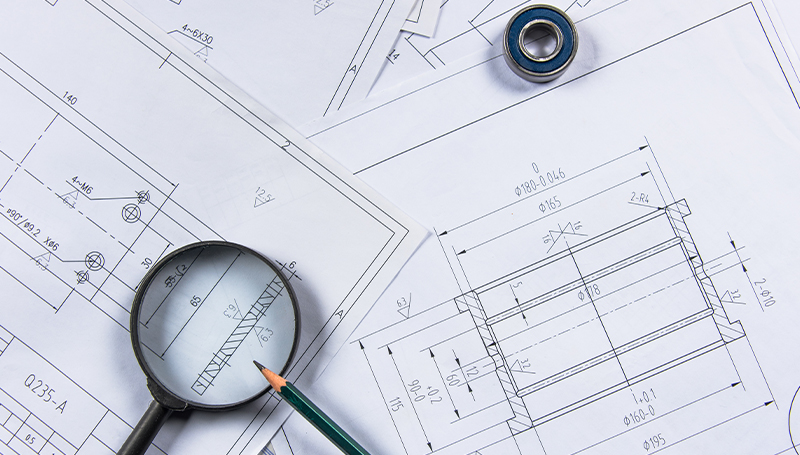
Key Components of Mechanical Drawings:

Electrical Drawings
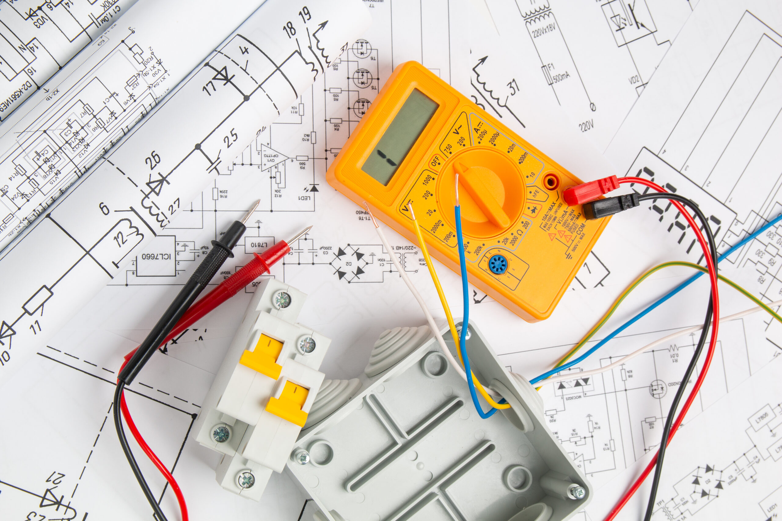
Key Components of Electrical Drawings:
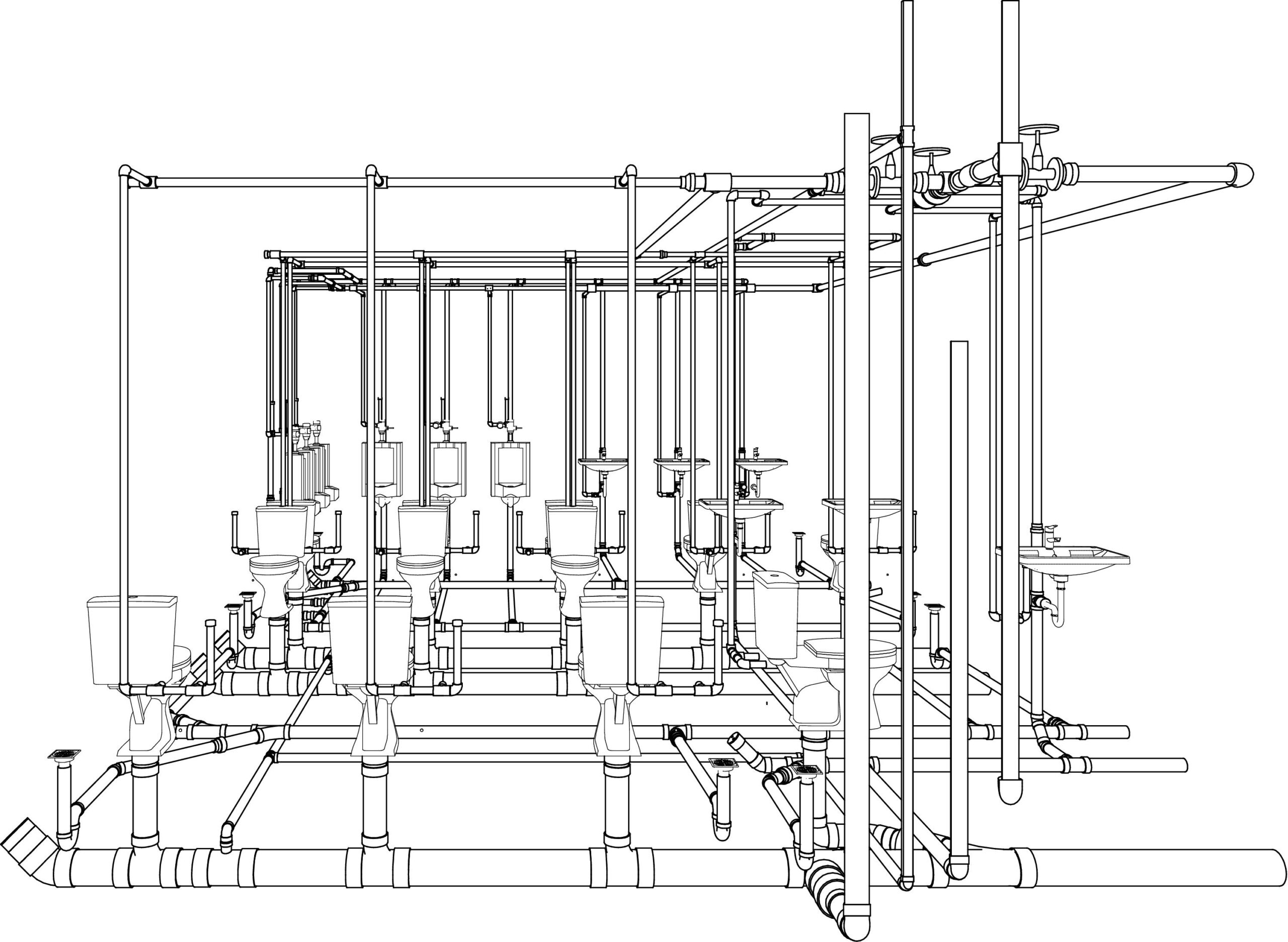
Plumbing Drawings
Key Components of Plumbing Drawings:
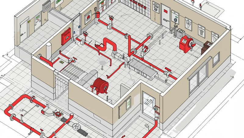
Fire Protection Drawings
Penetration Drawing
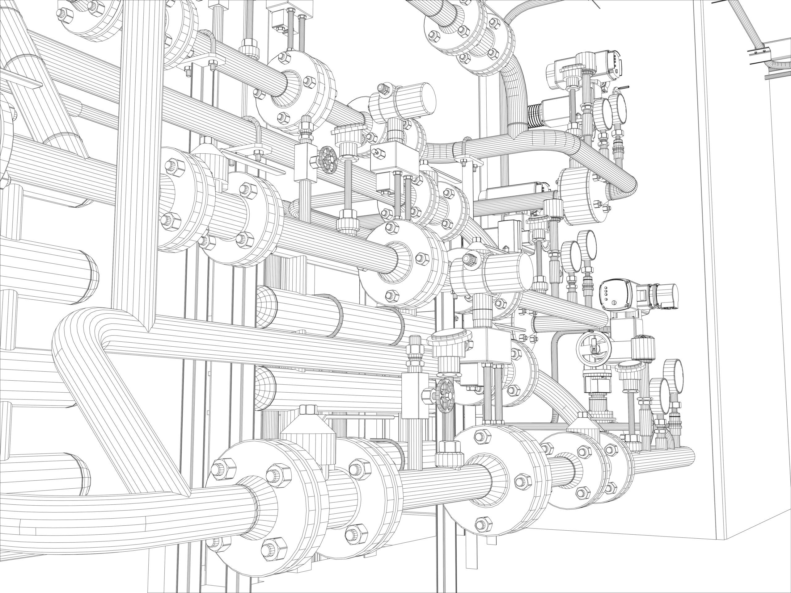
MEP Shop Drawing Detailing
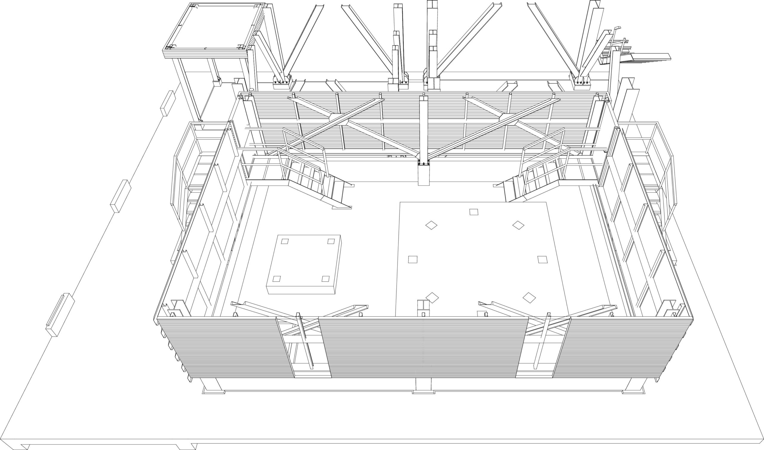
Block-out and Sleeve Drawing
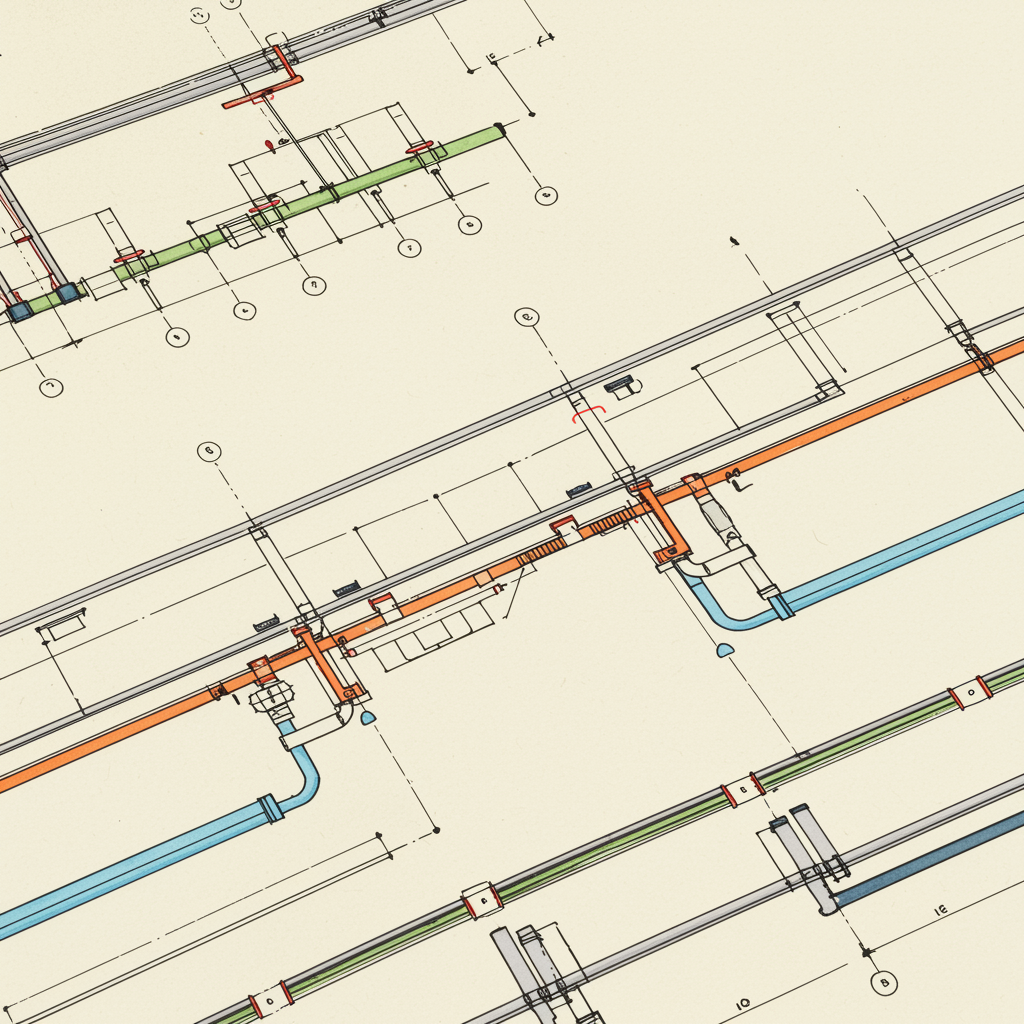
Pipe Spool Drawing
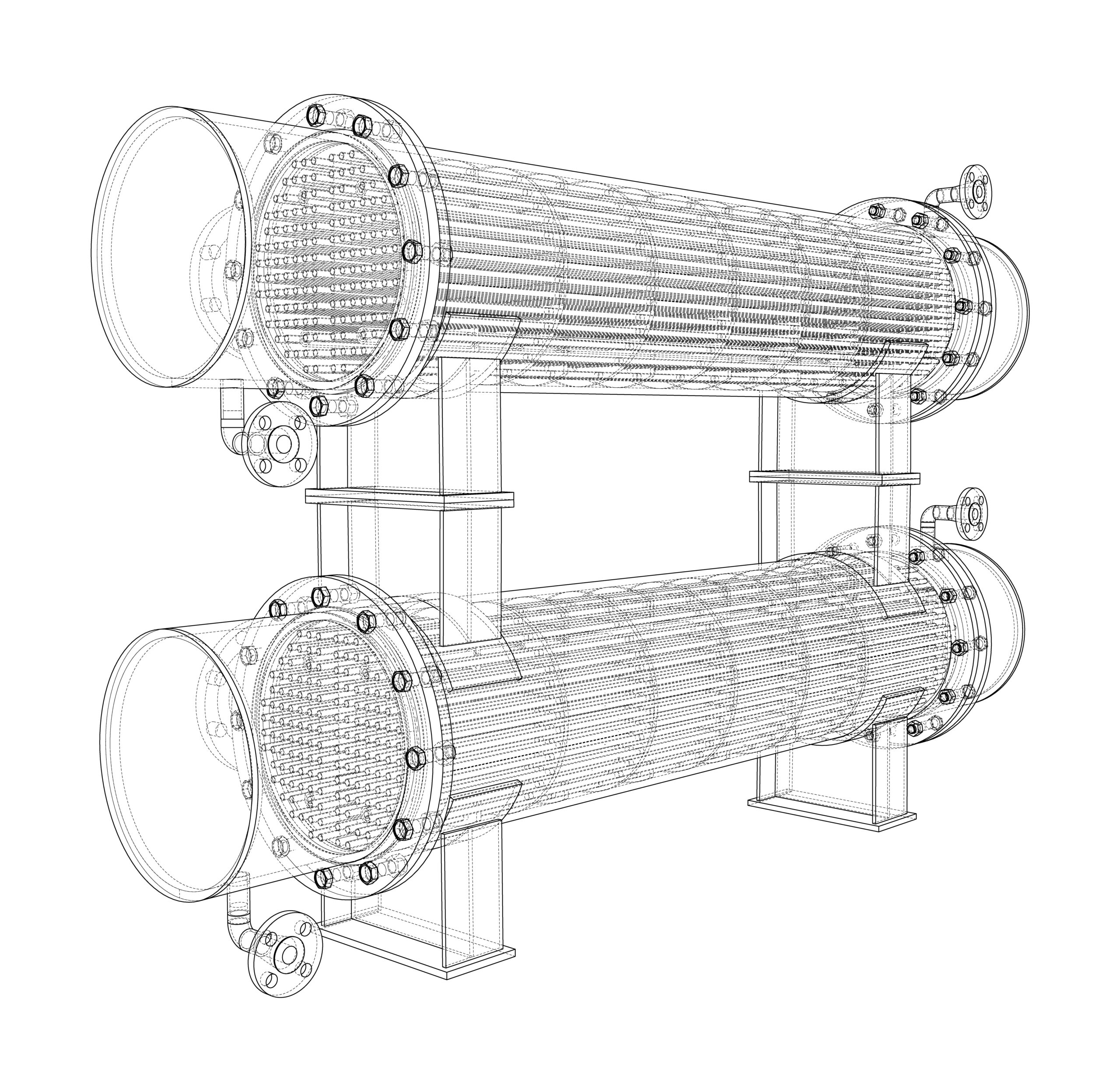
Petroleum Equipment. Vector rendering of 3d. Wire-frame style
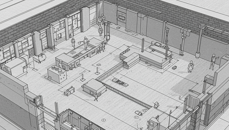
Coordination Drawing