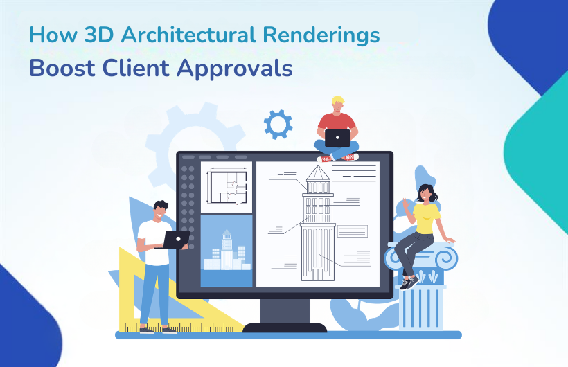
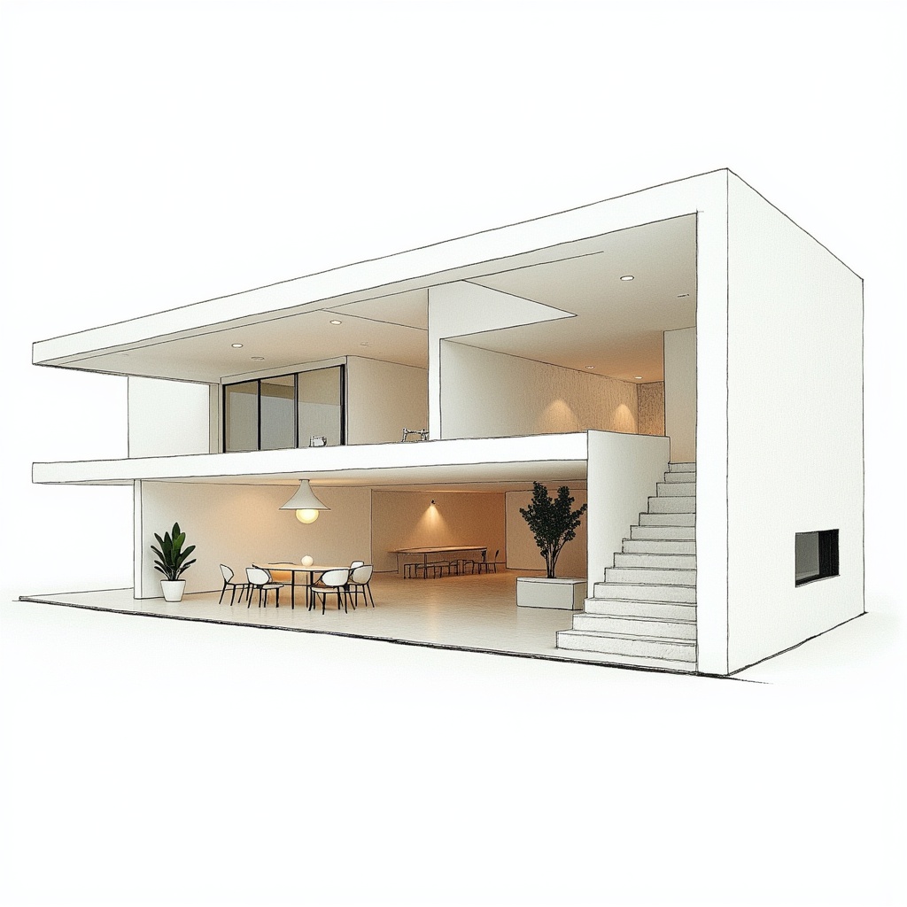
In today’s competitive real estate and construction market, winning client approvals quickly can determine the success of a project. Traditional 2D drawings and blueprints often leave room for confusion. This is where 3D Architectural renderings make a powerful difference.
At Monarch Innovation, we help architects, builders, and developers turn concepts into realistic visual experiences that accelerate decision-making and increase approval rates.
Why Clients Approve Faster with 3D Architectural Renderings
1. Clear Visual Communication
One of the biggest challenges in architecture is communication. Not every client understands technical drawings or construction documentation.
With photorealistic 3D visualization, clients can:
Instantly understand spatial design
Visualize room dimensions and proportions
See material finishes and colour schemes
Experience lighting effects
This eliminates guesswork and reduces back-and-forth revisions.
2. Emotional Connection with the Design
People make decisions emotionally first, logically second.
High-quality 3D exterior renderings and interior renderings create an emotional impact by helping clients imagine:
Living in the space
Hosting guests
Working in the office environment
At Monarch Innovation, we focus on realistic textures, natural lighting, and environment integration to create immersive architectural presentations that inspire confidence.
3. Reduced Design Revisions
When clients clearly see what they’re approving, misunderstandings drop significantly.
Benefits include:
Fewer change requests
Faster design validation
Streamlined construction workflow
Reduced project delays
This improves collaboration between architects, contractors, and stakeholders.
4. Competitive Advantage in Presentations
Whether pitching to investors or presenting to property buyers, 3D Architectural renderings enhance your professional image.
They:
Strengthen marketing presentations
Improve real estate pre-sales
Help secure funding approvals
Increase buyer confidence
Compared to flat drawings, 3D walkthroughs and virtual tours offer a modern, innovative experience.
5. Improved ROI for Developers
For real estate developers, approvals directly impact timelines and profitability.
This results in better return on investment and stronger project momentum.
How Monarch Innovation Delivers High-Impact 3D Architectural Renderings
At Monarch Innovation, our process combines technical precision with creative excellence:
1. Advanced 3D Modelling
We build accurate digital models based on architectural plans and construction details.
2. Realistic Lighting & Texturing
We apply photorealistic materials, natural shadows, and environment effects.
3. Client-Centric Customization
We tailor visuals according to branding, project goals, and target audience.
4. Fast Turnaround & Revisions
Our streamlined workflow ensures quick delivery without compromising quality.
Final Thoughts
In a world where visual impact drives decisions, 3D Architectural renderings are no longer optional — they are essential. They improve communication, build trust, reduce revisions, and significantly boost client approvals.
If you’re looking to enhance your architectural presentations and secure faster project approvals, Monarch Innovation delivers cutting-edge architectural visualization solutions designed for results.
Frequently Asked Questions
1. How do 3D Architectural renderings help in client approvals?
They provide a realistic visual representation of a project, helping clients clearly understand the design, reducing confusion, and increasing approval speed.
2. Are 3D renderings better than 2D drawings?
Yes. While 2D drawings are technically important, 3D renderings offer visual clarity, realism, and emotional engagement that improve decision-making.
3. Do 3D renderings reduce project revisions?
Absolutely. Clear visualization minimizes misunderstandings, leading to fewer design changes and faster project progress.
4. Can 3D Architectural renderings be used for marketing?
Yes. They are widely used in real estate marketing, investor presentations, brochures, websites, and social media promotions.
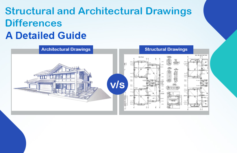
In the construction industry, accuracy, clarity, and proper coordination are essential for turning a concept into a fully functional structure. Two of the most important documents that guide this process are architectural drawings and structural drawings. Although both are created for the same project, their roles, technical depth, and objectives are different. Understanding structural drawing vs architectural drawing helps avoid design errors, delays, and costly onsite changes.
This blog explains the differences, features, purposes, and uses of both drawing types, along with an overview of essential construction drawing types used across modern projects.
What Are Architectural Drawings?
Architectural drawings serve as the visual and conceptual backbone of any construction project. They define the building’s overall look, spatial layout, aesthetics, and functionality. Architects prepare these drawings to communicate design intent to clients, consultants, and contractors.
Elevations – External views of a building from different sides.
Sections – Vertical cuts illustrating internal relationships between floors, rooms, and components.
Site Plans – Indicate building placement, landscape elements, pathways, parking and boundaries.
Finishing Details – Materials, textures, interior elements, and design finishes.
These drawings serve as a guide for the overall look and usability of the structure while maintaining compliance with regulatory and aesthetic standards.
Purpose of Architectural Drawings
Architectural drawings aim to:
Establish the design intent of the building
Help clients visualise the final structure
Provide references for contractors and engineers
Ensure compliance with building codes and zoning laws
Coordinate design across disciplines
Aid in cost estimation and project planning
In simple terms, architectural drawings define what the building will look like and how spaces function.
What Are Structural Drawings?
While architectural drawings focus on aesthetics and space planning, structural drawings focus on safety, stability, and material strength. Structural engineers develop these drawings to ensure the building can withstand loads, forces, and environmental conditions.
Key Features of Structural Drawings
Structural drawings usually include:
Foundation Plans – Footing sizes, depth, and reinforcement details.
Beam & Column Layouts – Load-bearing systems and connections.
Slab Designs – Thickness, reinforcement patterns, and strength specifications.
Structural Layout Drawings – Complete structural framework of the building.
These drawings are far more technical and calculation-driven compared to architectural drawings.
Purpose of Structural Drawings
Structural drawings aim to:
Ensure the building’s strength, stability, and safety
Define load-bearing members and their specifications
Communicate reinforcement detailing to contractors
Coordinate structural components with architectural layouts
Establish material requirements for concrete, steel, and other load-bearing elements
Prevent design failures and structural risk
Simply put, structural drawings define how the building will stand and how loads are transferred safely.
Structural vs Architectural Drawings: Key Differences
Architectural and structural drawings may appear similar on the surface, but they serve completely different functions. Recognising the difference ensures smoother project execution and avoids onsite conflicts.
MEP drawings ensure the seamless installation of essential building services.
Interior Design Drawings
Used for creating a functional and aesthetically appealing interior environment, they include:
Furniture layout plans
Ceiling designs
Lighting layouts
Material selection sheets
They help guide interior contractors and vendors.
Civil & Landscaping Drawings
Civil and landscape drawings include:
Road layouts
Drainage systems
Soil grading plans
Softscape and hardscape designs
They improve external functionality and environmental harmony.
Conclusion
Both architectural and structural drawings are essential for successful project delivery. Architectural drawings determine the building’s form, appearance, and spatial arrangement, while structural drawings ensure that the building stands strong and safe. Understanding structural drawing vs architectural drawing helps improve design coordination, reduce errors, and strengthen communication between teams.
As construction projects evolve, the importance of accurate, detailed, and coordinated drawings becomes even more critical. Partnering with experienced engineering and design experts like Monarch Innovation ensures high-quality drawings, faster project execution, and seamless collaboration.
FAQs
1. What is the main difference between architectural and structural drawings?
Architectural drawings focus on the building’s design and layout, while structural drawings focus on its safety and load-bearing structure.
2. Are structural drawings more detailed than architectural drawings?
Yes. Structural drawings contain technical specifications, reinforcement details, and calculations.
3. Who prepares architectural drawings?
Architects prepare architectural drawings.
4. What are shop drawings in construction?
Shop drawings are detailed fabrication drawings created by contractors or fabricators for manufacturing components like steel frames, HVAC ducts, or furniture.
5. Why do construction projects need different drawing types?
Because each drawing serves a different purpose, from design and structure to interior and MEP systems, ensuring smooth project execution.
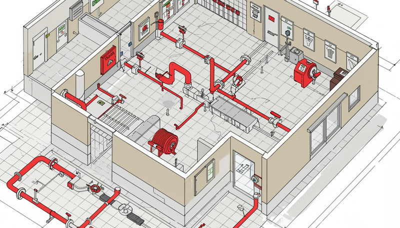
MEP drawings in construction focus on mechanical, electrical, and plumbing systems, ensuring building safety, functionality, and energy efficiency. It refers to the mechanical, electrical, and plumbing systems which mainly serve as the backbone of the construction works. MEP consists of Mechanical (HVAC systems), Electrical (power supply), and Plumbing (water supply and drainage). Revit MEP, AutoCAD, CADDUCT, Autodesk Inventor, and CAD PIPE are mainly used for preparing these drawings.
What is MEP Drawings?
MEP drawing construction visually communicates the construction and functionality of components, ensuring clarity and coordination across the construction industry. Expert CAD drafting companies use standard notation systems and measurement units to enhance clarity in coordination drawings. Detailed MEP drawings ensure proper installation of ductwork, plumbing, piping, electrical conduits, and fire protection systems without conflicts. Every building’s MEP drawing set is unique and generated after the installation of the building design documents.
Different Types Of MEP Drawings:-
1. Mechanical Drawings:
Mechanical Drawings are technical drawings that focus on the design, layout, and installation of mechanical systems in a building. These systems are primarily related to HVAC (Heating, Ventilation, and Air Conditioning), piping, and sometimes machinery used in industrial or commercial buildings. Mechanical drawings provide precise information on how these systems should be installed, maintained, and operated.
Key Components of Mechanical Drawings:
HVAC (Heating, Ventilation, and Air Conditioning) Layout: Shows the design and layout of HVAC systems, including ductwork, air handling units, diffusers, etc.
Ducting Layout: Specific drawing for duct routes, sizes, and airflow details.
Equipment Layout: Indicates the location of major mechanical equipment such as chillers, boilers, and cooling towers.
Piping Layout: Illustrates the piping routes for chilled water, hot water, steam, or other mechanical systems.
2. Electrical Drawings:
Electrical Drawings are detailed technical plans that represent the design, layout, and wiring of electrical systems within a building. These drawings are essential for the construction, installation, and maintenance of electrical infrastructure, ensuring that power is safely and efficiently distributed throughout a structure. Electrical drawings serve as a blueprint for electricians, engineers, and contractors, helping them to understand the electrical requirements and connections.
Key Components of Electrical Drawings:
Lighting Layout: Shows the positioning and specifications for lighting fixtures and controls.
Power Distribution Layout: Indicates the routing of electrical wiring and location of power outlets, panels, and switchboards.
Circuitry Diagram: Represents the wiring for electrical circuits, connections, and panel schedules.
Fire Alarm System Layout: Details the fire alarm devices, wiring, and control panels.
Low Voltage System Layout: Covers systems such as data, telephone, security, and AV systems.
3. Plumbing Drawings:
Plumbing Drawings are detailed technical plans that illustrate the layout, design, and installation of a building’s plumbing system. These drawings guide the construction and installation of piping, fixtures, drainage systems, and water supply, ensuring proper functioning and compliance with building codes. Plumbing drawings are critical for both residential and commercial projects, and they play a significant role in ensuring the safety, efficiency, and sustainability of water management within a building.
Key Components of Plumbing Drawings:
Water Supply Layout: Shows the layout of cold and hot water supply lines and fixtures like taps, sinks, and water tanks.
Drainage Layout: Provides details on the drainage system, including sewer lines, traps, and vents.
Sanitary System Layout: Focuses on the sanitary piping for toilets, wash basins, and other fixtures.
Gas Piping Layout: If applicable, shows the layout for gas pipes and appliances.
4. Fire Protection Drawings:
Fire Protection Drawings are specialized technical plans that detail the design and layout of fire protection systems within a building. These drawings are crucial for ensuring the safety of occupants and property by effectively detecting, suppressing, and controlling fires. Fire protection drawings help guide the installation, maintenance, and inspection of fire safety systems to meet regulatory standards and building codes.
5. Penetration Drawing
A Penetration Drawing is a specialized type of technical drawing used in construction, particularly in projects involving MEP (Mechanical, Electrical, and Plumbing) systems. It shows how various systems (pipes, ducts, conduits, or cables) pass through structural elements of a building, such as walls, floors, and ceilings. This ensures that the penetrations are correctly located and sealed for safety, functionality, and compliance with building codes.
6. MEP Shop Drawing Detailing
MEP Shop Drawing Detailing refers to the highly detailed and precise set of drawings used during the construction phase to represent the installation of mechanical, electrical, and plumbing systems. These shop drawings are different from design drawings as they provide a more granular view of the components and their installation, based on actual site conditions and contractor preferences.
7. Block-out and Sleeve Drawing
These drawings are useful for cement and steel contractors. The drawings are of great help when it comes to determining where to leave space on the floor and ceiling cutouts. Sleeve drawings ensure proper placement of holes between floors and walls for piping and ductwork.
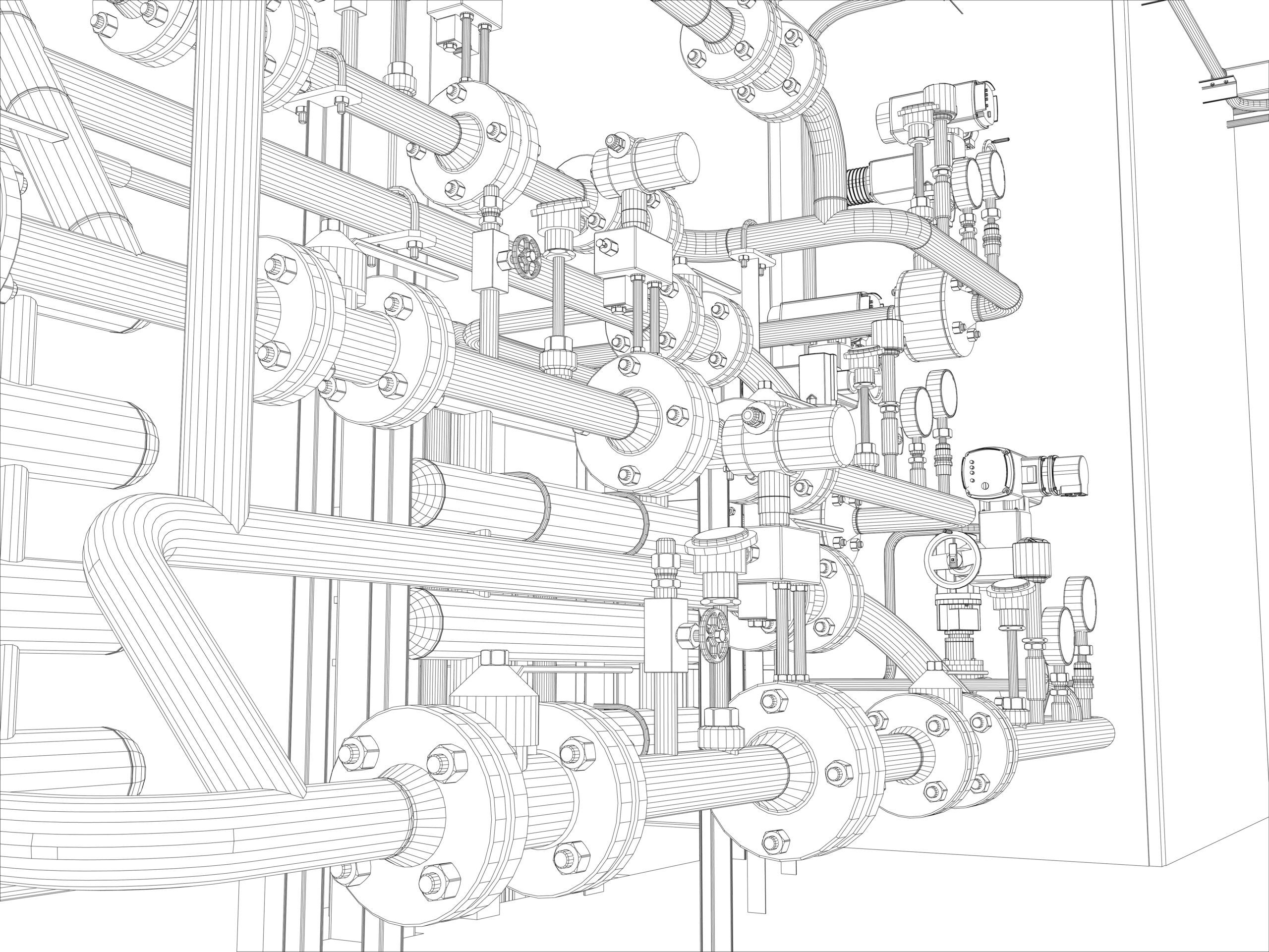
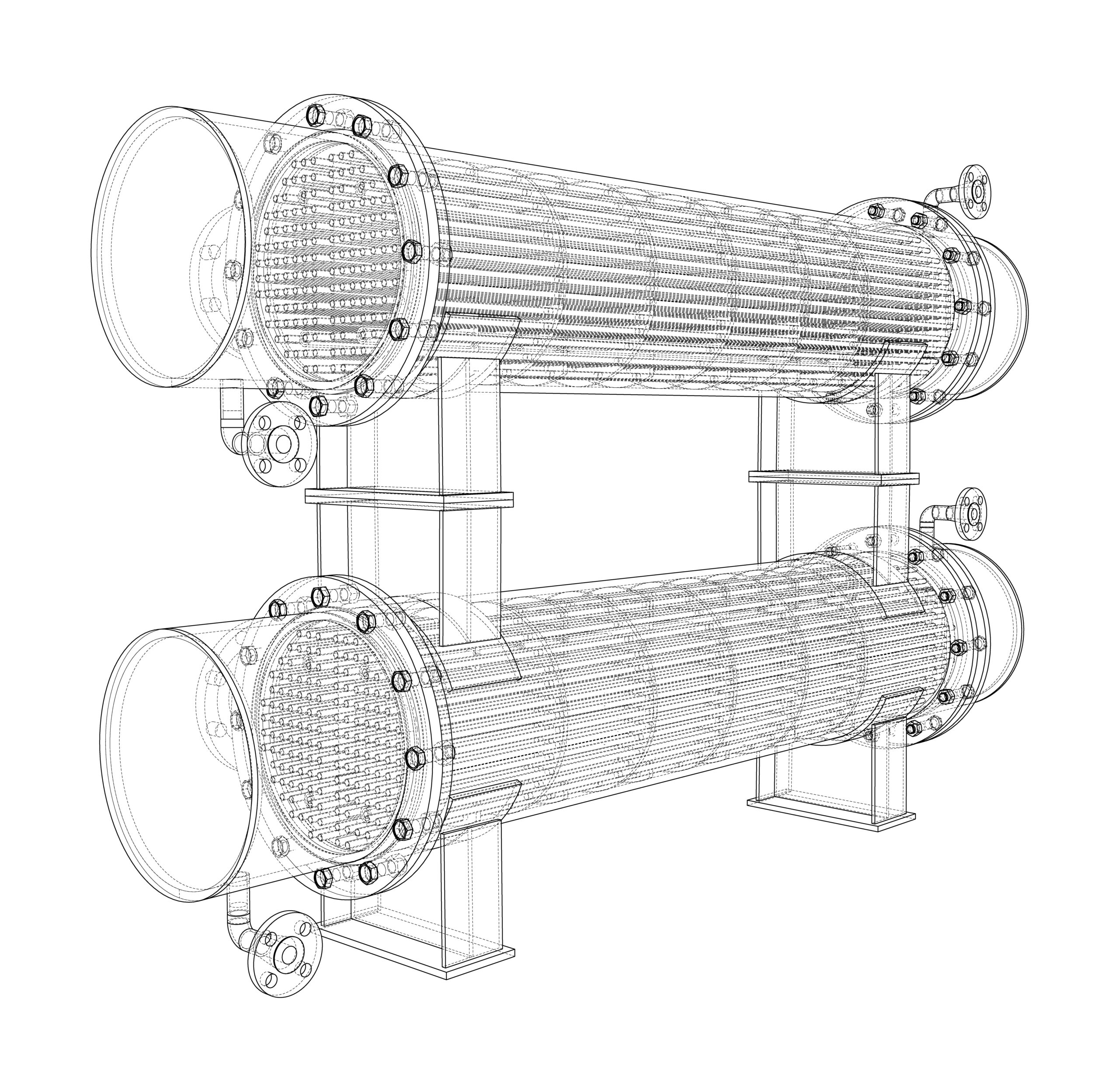
8. Pipe Spool Drawing
Petroleum Equipment. Vector rendering of 3d. Wire-frame style
A spool is an assembly of pipes that includes components pre-fabricated in the workshop for installation and later shipped to the site for assembly. These drawings guide plumbers in understanding the required tasks. Spools connect at various junctions throughout the structure. The drawings provide essential information to help fabricators manufacture and assemble the spool accurately. A spool drawing compiles detailed information about all welded parts into a single, comprehensive illustration.
9. Coordination Drawing
Coordination is very important for the success of any building project. It simply means avoiding physical conflicts in the layout of the equipment and the routing of ducts, electrical piping, and drainage pipes through the building. When any building project has intense MEP requirements, the risk of interference problems is high. Elimination of coordination problems is a prerequisite for starting the construction work for projects with an intense MEP system. Coordination drawings are necessary to begin the construction work and eliminate any physical conflicts.
10. As-built Drawing
As-built drawings document the final construction, reflecting changes made during the process, unlike design or shop drawings.
Unlike original design or shop drawings, which represent the intended design, as-built drawings document the completed project as it exists, including any deviations from the original plans. These drawings are essential for future maintenance, repairs, and renovations.
Conclusion
MEP drawings are essential for ensuring accuracy, efficiency, and seamless coordination in construction projects. From HVAC systems to plumbing and electrical planning, precise MEP drafting minimizes conflicts and optimizes building performance. At Monarch Innovation, our expert team is committed to delivering high-quality MEP BIM services that enhance project execution and long-term sustainability.
Contact us for all your MEP BIM Services requirements, we at Monarch Innovation are happy to help.
FAQs
1. What is MEP in HVAC?
MEP in HVAC refers to the integration of the mechanical, electrical, and plumbing systems required for the proper functioning of HVAC systems in buildings.
2. What is MEP Specification?
MEP specifications refer to the detailed requirements and guidelines for the mechanical, electrical, and plumbing systems that are part of a construction project. These specifications define the standards, materials, equipment, and installation procedures needed to ensure MEP systems meet the design intent and function properly.
3. What is the role of MEP in the construction industry?
MEP plays a crucial role in the construction industry as it is responsible for the design, installation, commissioning, and maintenance of the mechanical, electrical, and plumbing systems that are necessary for the safe and efficient operation of buildings.
In the world of construction, the acronym MEP stands for Mechanical, Electrical, and Plumbing. These are critical components in any building project, essential for ensuring functionality, safety, and sustainability. In the intricate dance of construction planning, MEP plans play a starring role, guiding architects engineers, and contractors through the maze of challenges inherent in bringing a building from concept to reality. As we delve into the importance of MEP plans in construction projects in 2024, we’ll explore their significance, evolution, and the crucial role they play in shaping modern infrastructure.
What are MEP Plans?
MEP plans serve as the architectural roadmap for the installation and coordination of mechanical, electrical, and plumbing systems in buildings and industrial projects. These comprehensive blueprints provide detailed insights into the design, layout, and specifications of each system, guiding architects, engineers, and contractors through the intricacies of construction.
Components of MEP Plans
Mechanical: The mechanical aspect of MEP plans encompasses HVAC systems, ventilation, and air conditioning. Engineers meticulously design these systems to optimize indoor air quality, thermal comfort, and energy efficiency within a building.
Electrical: MEP electrical plans outline the electrical distribution network, encompassing lighting, power outlets, and electrical panels. With a focus on sustainability, modern electrical plans incorporate renewable energy sources and energy-efficient technologies to minimise environmental impact.
Plumbing: Plumbing systems detailed in MEP plans cover water supply, drainage, and sewage disposal. These plans ensure the efficient flow of water throughout the structure while integrating eco-friendly fixtures and water conservation measures.
The Significance of MEP Plans
The importance of MEP plans in construction cannot be overstated. These blueprints serve multiple purposes, including:
Coordination and Integration: MEP plans facilitate seamless coordination and integration of mechanical, electrical, and plumbing systems, minimising conflicts, and redundancies during construction.
Efficiency and Cost Savings: By pre-emptively addressing design conflicts and optimising system layouts, MEP plans reduce rework, delays, and cost overruns, ultimately enhancing project efficiency and profitability.
Occupant Comfort and Safety: Well-designed MEP systems contribute to optimal indoor air quality, lighting, and thermal comfort, creating a conducive environment for occupants while adhering to safety standards and regulations.
Sustainability: With a growing emphasis on environmental stewardship, MEP plans incorporate sustainable design principles, such as energy-efficient technologies and water conservation measures, to minimise the carbon footprint of buildings.
Understanding MEP Plans
MEP plans form the backbone of any construction endeavour, offering a comprehensive compilation of drawings, designs, and specifications vital to the mechanical, electrical, and plumbing systems within a building. These plans serve as a meticulous roadmap, guiding the installation, operation, and maintenance of these indispensable systems while ensuring seamless integration with the overarching architectural framework.
MEP Plans in Construction
Foundational to every construction venture is the imperative for robust MEP plans. Whether erecting a soaring skyscraper, an expansive industrial complex, or a cosy residential haven, the triumph of the project pivots on the efficiency and dependability of its mechanical, electrical, and plumbing systems. MEP plans stand as the cornerstone for these systems, delineating intricate details ranging from HVAC ductwork and electrical wiring to piping layouts and fire suppression systems.
MEP Plan Architecture
The architectural composition of MEP plans embodies a delicate equilibrium between functionality and aesthetics. While compliance with building codes and regulations is paramount, there exists a concerted effort towards seamlessly integrating these components into the overall design ethos. Contemporary MEP plan architecture underscores efficiency, sustainability, and occupant comfort, assimilating cutting-edge technologies and eco-conscious building practices to forge structures that marry form with function.
MEP Design Plans
Crafting MEP plans necessitates a collaborative, multidisciplinary approach wherein architects, engineers, and designers synergize to optimise system performance and efficiency. From the selection of energy-efficient HVAC systems to the orchestration of lighting layouts conducive to occupant well-being, every facet of MEP design plans is meticulously calibrated to yield edifices that exude both practical utility and aesthetic allure.
Construction MEP Plans
In the crucible of the construction phase, MEP plans emerge as guiding beacons for contractors and tradespeople, furnishing precise directives on system installation, connection, and commissioning. Clarity and precision in MEP plans streamline the construction continuum, mitigating errors, delays, and cost escalations while ensuring adherence to project timelines and quality benchmarks.
The Evolution of MEP Plans: Embracing Innovation
The realm of MEP plans is not static but rather dynamic, continually evolving in response to technological advancements and industry trends. One such transformative force is Building Information Modeling (BIM), which has revolutionised the landscape of MEP planning and execution. Through BIM, stakeholders collaborate within a virtual environment, facilitating seamless coordination, clash detection, and performance optimization across mechanical, electrical, and plumbing systems.
Embracing Sustainability:The Green Imperative
In tandem with the global push towards sustainability, MEP plans have assumed a pivotal role in fostering eco-friendly building practices. Integration of renewable energy sources, energy-efficient HVAC systems, and water-saving plumbing fixtures exemplify initiatives aimed at reducing carbon footprints and enhancing environmental stewardship. Moreover, sustainable MEP planning not only aligns with regulatory mandates but also yields long-term cost savings through reduced energy consumption and operational expenditures.
Enhancing Resilience: Adapting to Changing Needs
As urbanisation burgeons and climate change exerts its toll, the resilience of built infrastructure emerges as a pressing concern. MEP plans, therefore, must not only address present needs but also anticipate future challenges. Resilient design principles, encompassing redundancy, flexibility, and adaptability, imbue MEP plans with the capacity to withstand unforeseen disruptions while ensuring the continuity of essential services.
Emerging Trends in MEP Design and Planning
As technology continues to advance, several trends are shaping the future of MEP drawing, design and planning:
BIM Automation Services for MEP Design
Building Information Modeling (BIM): BIM technology enables stakeholders to create digital representations of MEP systems, facilitating collaborative design, clash detection, and lifecycle management.
Prefabrication and Modularization
MEP BIM Services: Prefabricated MEP components and modular systems are gaining traction, offering enhanced quality control, shortened construction schedules, and reduced onsite labour requirements.
Smart Building Technologies
MEP Electrical Plans: Integration of IoT (Internet of Things) devices, sensors, and automation systems into MEP designs enhances building performance, operational efficiency, and occupant comfort.
Conclusion
MEP plans are crucial for the seamless integration of mechanical, electrical, and plumbing systems in modern construction projects. As the industry evolves, embracing innovation and sustainability becomes imperative.
Partnering with experienced firms like Monarch Innovations ensures top-notch MEP design solutions. With their commitment to excellence, Monarch Innovations drives construction projects towards efficiency and success.
By leveraging expertise and staying updated with emerging trends, stakeholders can navigate construction complexities with confidence. With Monarch Innovations leading the way in MEP design, projects can achieve unparalleled levels of efficiency and sustainability.
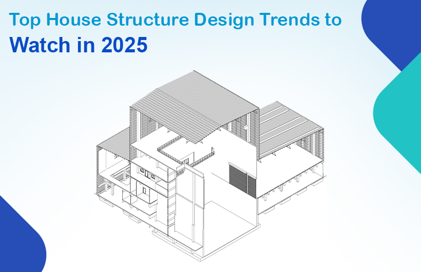
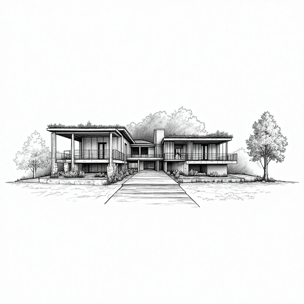
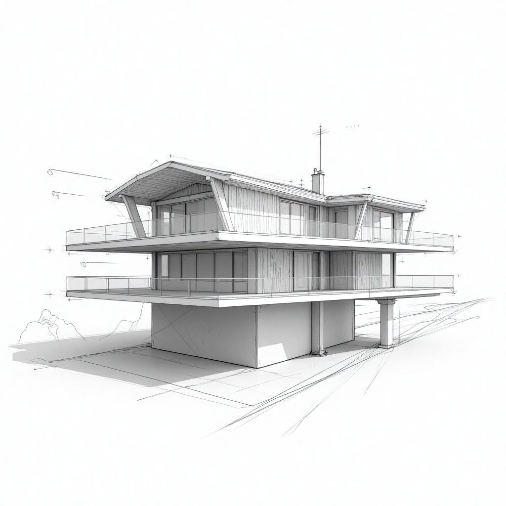
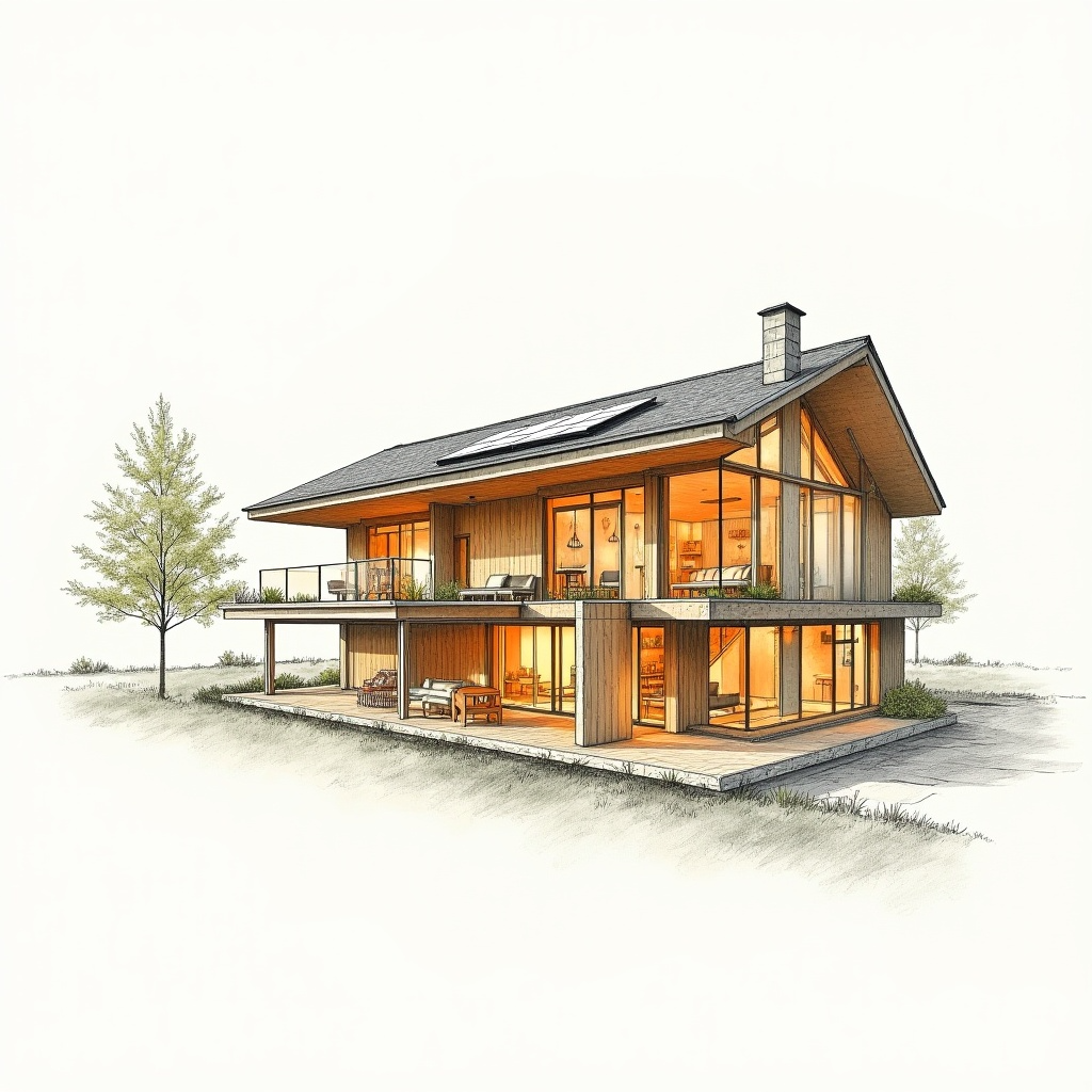
The way we design and build our homes is evolving fast, and 2025 is set to be a year of bold changes, smarter choices, and more sustainable building practices. Whether you’re dreaming of your future home or planning a renovation, understanding the structure of house design trends can help you make decisions that are both stylish and future-ready.
Let’s explore the top 10 house structure designs that are gaining popularity and shaping the homes of tomorrow.
1. Sustainable Structures with Eco-Friendly Materials
Homeowners and builders are putting sustainability first. Instead of traditional bricks and cement alone, materials like bamboo, cross-laminated timber, and recycled metal are being used in the structure of house design. These eco-conscious choices reduce environmental impact while improving the home’s insulation and durability.
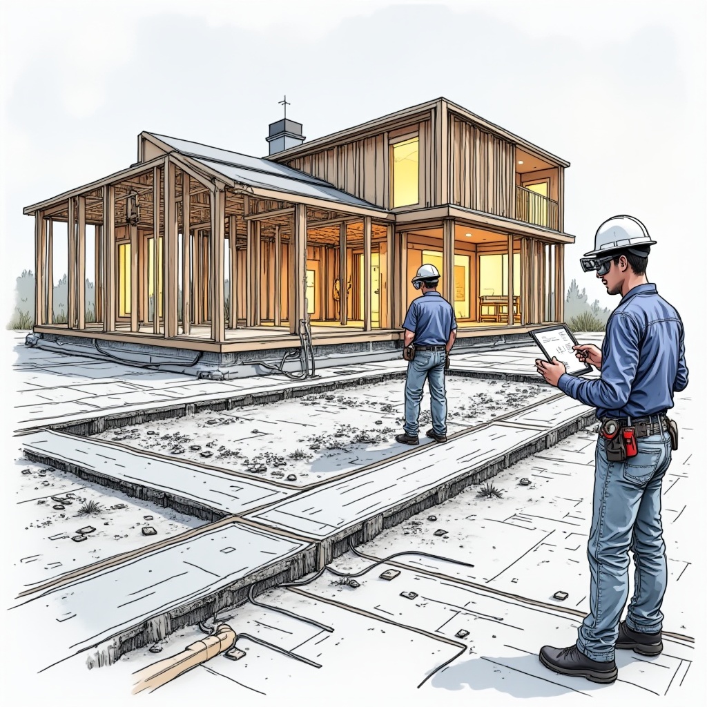
2. Technology-Ready Structural Design
Smart homes are no longer just a luxury—they’re becoming the standard. Today’s house structures are being designed to support tech from the ground up. Built-in conduits, smart lighting systems, integrated power management, and automated ventilation are being accounted for during early construction, making homes more efficient and easier to manage.
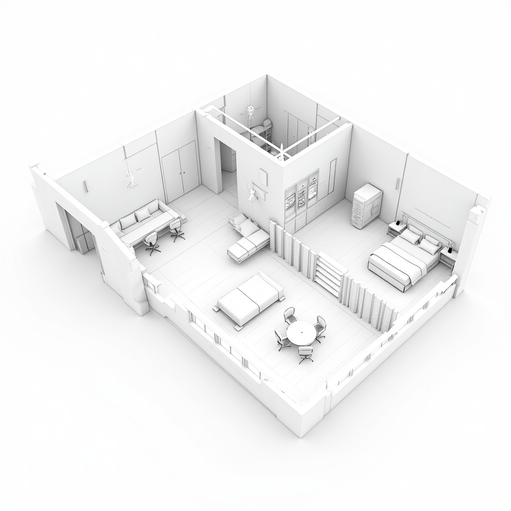
3. Open and Flexible Layouts
In 2025, functionality is key. Instead of rigid, single-use spaces, more homeowners want open-concept designs that can change with their needs. The structure often includes movable partitions, sliding doors, and load-bearing walls placed strategically to allow future interior customization.
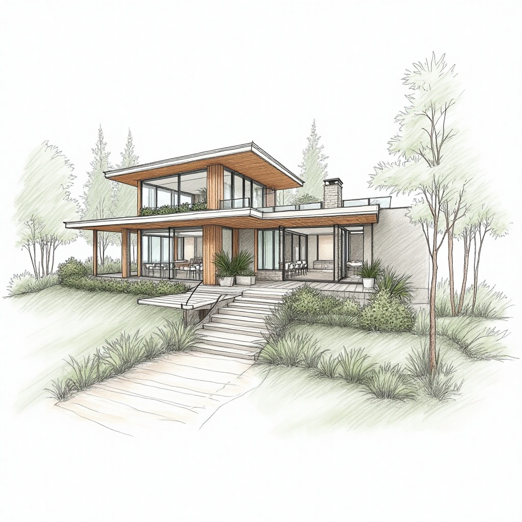
4. Biophilic-Inspired Structural Design
Bringing nature indoors is no longer just about decor. The structure of house design is being shaped around biophilic principles—think of homes that are physically built to allow more natural light, cross-ventilation, indoor gardens, and visual connections to the outdoors. This approach improves mental wellness and indoor air quality while creating stunning aesthetics.
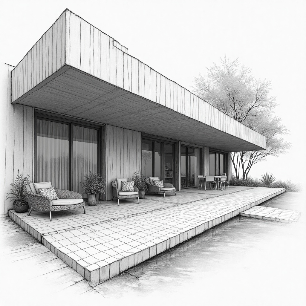
5. Minimalist Architecture with Smart Space Planning
The minimalist design trend continues, but in 2025, it’s more practical than ever. Architects build homes with a ‘less is more’ approach—using fewer walls, clean lines, and multifunctional structures. Their designs support clutter-free living and enhance space usage, especially in smaller homes or urban environments.
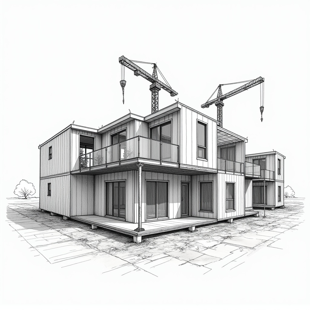
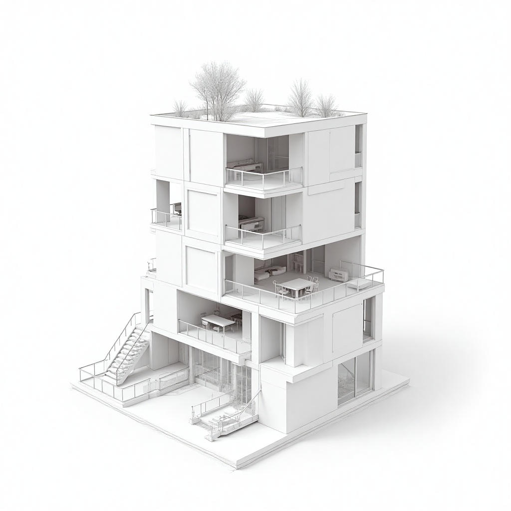
6. Modular and Prefabricated Home Structures
Prefabricated construction has made major strides in recent years. Homebuilders now view modular homes as high-quality, customizable options. They precision-engineer the structure of house design, manufacturing individual sections off-site and assembling them on location. It saves time, reduces waste, and allows for flexible design.
7. Multi-Functional Zones for Modern Living
As remote work and hybrid lifestyles become the norm, house structures now account for diverse use cases. Think of built-in office spaces, home gyms, or adaptable guest rooms. The architecture supports easy division between work and relaxation, with design elements like double-insulated walls for soundproofing or sliding room dividers.
8. Disaster-Resilient Structural Engineering
With climate change leading to more frequent natural disasters, resilience has become a top priority. The structure of house design now includes storm-resistant roofs, elevated foundations in flood zones, earthquake-resistant frames, and fireproof materials, especially in disaster-prone regions. Architects integrate these features without compromising aesthetics.
9. Energy-Efficient Structural Systems
Designers and builders now optimize the building itself for energy efficiency, not just the smart appliances. Features like thermal insulation, airtight sealing, solar-ready rooftops, and optimized window placement are part of the structural blueprint. These elements help reduce electricity bills and keep the home comfortable year-round.
10. Compact Designs with Maximum Utility
People want homes that use every inch wisely, especially as urban land becomes limited. Compact homes with cleverly designed layouts—like vertical construction, rooftop gardens, and built-in storage—are in high demand. The structure of house design in 2025 supports comfort, convenience, and community, even in tighter footprints.
Final Thoughts
The structure of house design in 2025 is all about creating homes that are smarter, more adaptable, and built to last. From energy-saving features to flexible layouts and modular construction, today’s trends reflect how homeowners are thinking ahead—designing not just for now, but for the future.
If you’re ready to bring these trends into your next project, partner with a team that understands both innovation and execution. At Monarch Innovation, we combine design expertise with engineering excellence to deliver future-ready solutions in home construction.
Construction drawings are used for a wide variety of reasons and applications in construction and architectural projects and activities.
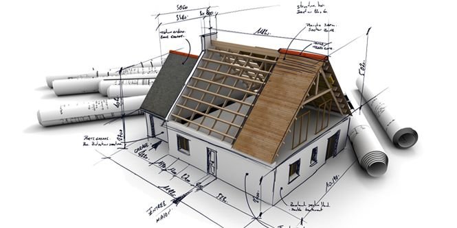
What is a construction drawing?
It is a graphical representation of what will be built, how it will be laid out, the components, framework, and dimensions. There is a construction drawing highlighting the details of every aspect of a construction project.
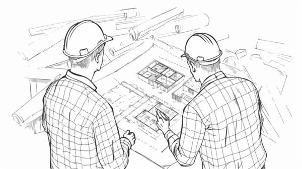
Construction Drawings including each of its subtypes are helpful to different groups of workforce assigned with doing or overlooking the various tasks that make up a construction project.
How are construction drawings made?
Rarely are construction plans drawn by hand anymore. They are either sketched and rendered using computer-aided drafting such as computer-aided design (CAD) software. And in recent times, Building Information Modeling (BIM) software has made it easy to render and visualize in detail the virtual construction models (VCM).
To know more about BIM services, budgeting, and how they can benefit your project, reach out to us at Monarch Innovation for all queries, assistance, and collaborations.
Top most common types of Construction drawings used regularly in construction industries.
Architectural Drawings
Architectural Drawings are drawings work that is used in building drawings to depict the dimensions, depth, and layout of the actual building, before beginning the construction. Architectural Drawings act as a blueprint construction, drawn to scale, to help the engineers visualize the project.
Various types of Architectural Drawings commonly used are:
1. Block Plan
This drawing gives a layout of the site or the buildings in the surrounding area, laid out on a map drawn to scale.
It gives a firsthand idea of the roads, boundaries, and other such details that are necessary to understand where your construction site lies.
It helps the person dealing with your construction plan or project request to understand what and where you are proposing it and help you out with it too.
Block plans are made in relation to Ordnance Survey Maps and the recommended scales used are 1:2500, 1:1250, or 1:500.
2. Foundation plan
Not to be mistaken for just the ground or basement floor plan. Foundation Plans are drawing work to render any of the floors of the building being constructed. They help visualize the dimensions, size, shape, height, and configuration of rooms/stairs/landings with each other.
Foundation Plan
3. Floor plans
In-depth rendering of the layout of the rooms for each floor. It describes in 2D the orientation of rooms and components to each other. Floor plans may or may not be utilized in commercial or non-commercial building projects, but it is necessarily still made as part of the drawing work.
Floor plan designed building drawing
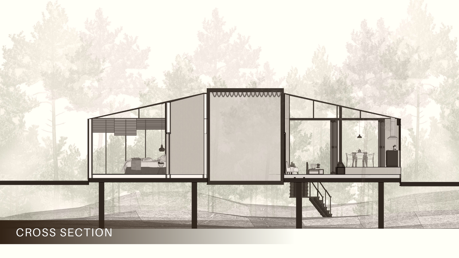
4. Sectional Drawings
These are drawings that depict a part or whole of the framework in sliced form. It helps understand the measurements of various building components with each other, the materials used in the construction of those components, the height, depth, and hollowness, etc.
Sectional Drawing
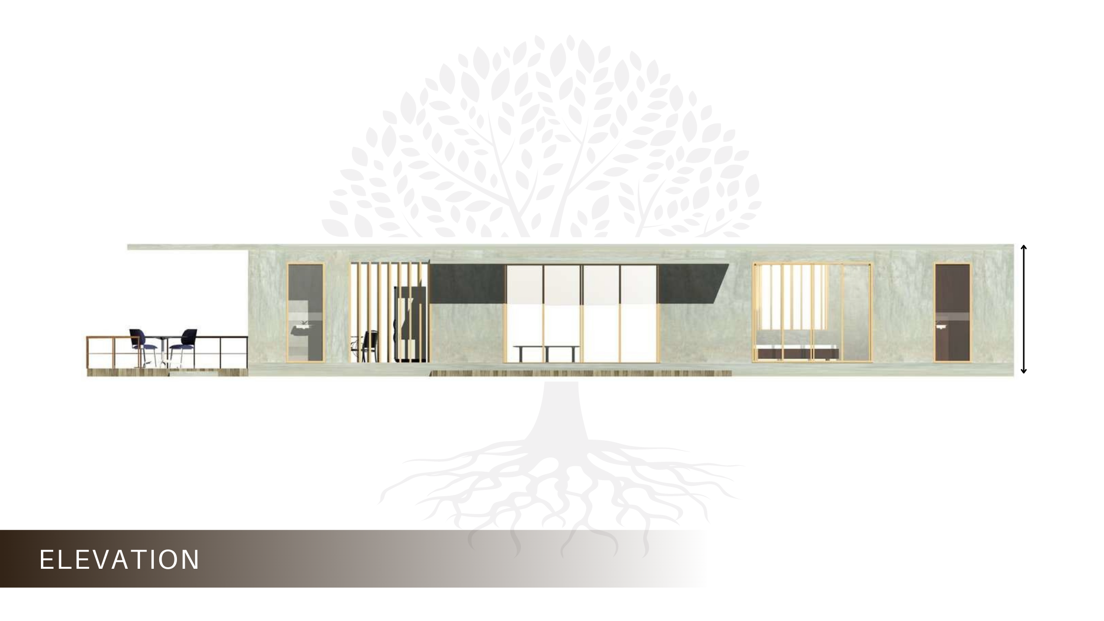
5. Elevation Drawings
These architectural drawings offer an aesthetic overview of the various components of the building such as columns, windows, and doorframes. It also helps understand the relative surface, internal markings, and relative height of these different components to each other.
6. Site Plan
A site plan is a detailed drawing that shows the entire construction site with property boundaries, existing structures, proposed new building locations, site grading/topography, and other site features like landscaping, parking areas, utilities, etc.
7. Isometric Drawing
An isometric drawing is a type of 3D parallel projection used to represent objects pictorially. It shows three sides of an object with the vertical lines projecting at a 30-degree angle and the horizontal lines projecting at a 30-degree angle.
8. Axonometric Drawings
Axonometric drawings are types of 3D parallel projections that show an object in an oblique/angled view. They include isometric, dimetric, and trimetric drawings depending on the exact angle used for the horizontal and vertical lines.
9. Presentation Drawings
Presentation drawings are highly detailed renderings or 3D models used to communicate and visualize the design intent for clients, stakeholders, and approving authorities. They showcase the appearance, materials, and aesthetic qualities of the project.
10. Survey Drawings
Survey drawings represent the existing conditions on a construction site based on detailed field survey data. They show site topography, boundaries, existing structures, underground utilities, and other existing features crucial for planning new construction.
11. Location Drawings
Location drawings are used to indicate the specific position or location of building components, systems like HVAC ducts, plumbing pipes, electrical conduits, etc. within the overall construction. They help avoid conflicts during installation.
12. Assembly Drawings
Assembly drawings illustrate in detail how different components and materials fit together during construction. They provide crucial information on the sequence, connections, and relationships between various building parts to guide proper assembly.
13. Parametric Drawing
A parametric drawing is created using parametric modeling software that allows the drawing views to automatically update when design parameters like dimensions or specifications are changed. This ensures consistent, coordinated drawings across all sheets.
14. Design Drawing
Design drawings are conceptual drawings that architects create early in the design process to explore, develop, and communicate design ideas and concepts to clients before moving to more detailed stages. They convey the building’s overall form, mass, and character.
15. Reflected Ceiling Plan
A reflected ceiling plan is a drawing that shows the layout of the ceiling as if it’s viewed from above by someone standing in the room looking upwards. It depicts ceiling-mounted elements like light fixtures, diffusers, speakers, etc.
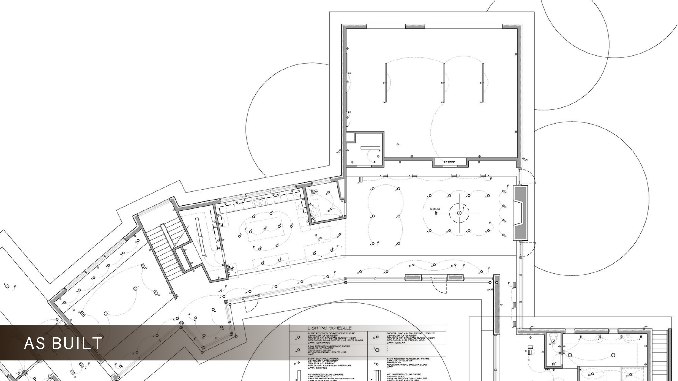
16. Record /As-built Drawings
Record drawings, also called as-built drawings, are the final set of drawings updated to incorporate all the construction changes, modifications, and as-built conditions from the actual construction process. They document the constructed project accurately.
Structural Drawings
Structural Drawings also serve as civil engineering drawings. They are useful in understanding the physical nitty-gritty of a building framework. They act as a structural design guide for the workers and on-site engineers. Common types of structural drawings are:
17. General Note
An overview of all the codes, procedures, abbreviations, etc required to give a comprehensive guide to getting to work on the construction site. This includes concrete mix, details for other structural drawings, lengths and construction types of each component, etc.
18. Excavation Drawing
This civil engineering drawing describes the dimensions and positions for the excavation process prior to the actual building work. It covers details like tunneling, shafts, removal of soil, grid plans, etc. required to start the groundwork.
19. Column Layouts
These structural drawings include the layouts of the way columns will be laid out. It makes it easier for contractors to plan the layout of the building and start the process by identifying the position and distance between columns across the floor.
20. Beam Layouts
It includes all the beam-like structures, such as the ones supporting the roof and the windows, or the beams used for strengthening purposes. They are designed for each floor and cover the length, height, material, etc.
21. Roof slab layouts
this civil engineering drawing describes the exact dimensions of all the slabs required for roofs or slants. It can be designed over AutoCAD software as it requires precision and data.
22. Section Plan
A section plan is a drawing that shows a cross-sectional vertical or horizontal view through the building by cutting through it. Section plans clarify the internal construction, framing, and relationships between different structural elements.
23. Detail Drawings
Detail drawings are large-scale drawings focused on specific construction details and connections between different structural components. They provide in-depth, magnified information crucial for installation and assembly by showing reinforcements, fasteners, dimensions, etc.
24. Component Drawing
Component drawings focus on providing comprehensive details and dimensions of individual structural elements like beams, columns, footings, etc. They serve as a reference for manufacturing, fabrication, or on-site construction of these components.
25. Column Layout
A column layout plan indicates the locations of all structural columns in the building along with the column gridlines and dimensions. It helps ensure proper positioning and installation of columns during construction.
26. Plinth Beam Layout
The plinth beam layout plan shows the layout, positions and dimensions of all plinth beams or grade beams that will be constructed below and support the load-bearing walls at the foundation level.
27. Lintel Beam Layout
A lintel beam layout plan depicts the locations, sizes, and geometry of all lintel beams provided over wall openings like doors, windows, etc. to transfer loads across those openings safely.
28. Roof Beam Layout / Shuttering
The roof beam layout plan shows the framing layout for supporting the roof structure with dimensions for beam sizes and spacing. The shuttering layout indicates formwork patterns/positioning for concrete roofs.
29. Framing Plan
A framing plan is a structural drawing that illustrates all the load-bearing, framed elements in the building like floors, walls, and roofs. It clarifies the overall framing system, member sizes, connections, and relationships.
30. Engineering Drawing
An engineering drawing is a technical drawing produced by structural engineers with precise dimensions, calculations, and specifications related to the building’s structural design, analysis, and detailing following relevant engineering codes.
Engineering Drawing
31. Installation Drawings
Installation drawings provide clear instructions and details guiding the installation processes for prefabricated structural components or building systems manufactured off-site for easy assembly on the construction site as per design specifications.
MEP Drawings
32. Electrical drawings
Most residential construction drawings or commercial construction drawings require a functional outline of the number of power outlets, light fixtures, fan fixtures, etc. They also include the wiring pattern and details about the electrical load it can carry. Common details included in Electrical Drawings are:
Earthing layout
Light fixture layout
Generator and other equipment
Cable tray layout
Hazardous area classifications
Lighting protection system
Just like electrical layouts, plumbing is another part of any residential or commercial construction drawing that marks the points where plumbing components need to be set up. Space is left here accordingly for further pipe and sanitary ware fixtures to be added once the structural component is finished. Plumbing drawings commonly include:
Pipes – water pipes, drainage pipes, internal pipes
Material of pipes
Outlet points – taps, sinks, tanks, etc
Position and location of pipes and outlets
33. HVAC/Mechanical Drawings
These are known as mechanical construction drawings. They provide details and a design framework for heating and ventilation systems in a building. Central heating/cooling, air conditioning vents, ventilators, etc are all included according to the need and site of the building plans. Builders use these design constructs in their process accordingly.
34. Piping Spool Drawings
Piping spool drawings are detailed drawings focused on specific prefabricated sections of pipes called spools used in industrial piping systems. They show precise dimensions, connections, and routing of these spool sections.
35. Firefighting Drawings
In today’s construction systems, safety design is paramount. Firefight Drawings are also a part of blueprint drawings of a building that allocate points for fire hoses, fire escapes, water outlets, sandbags, or any other fire safety equipment required by the regulatory body overseeing the project.
Additional Drawing Types
36. Production Drawings
These Construction Drawings are used to convey functional information to the workers and engineers on site. It describes the materials, the assembly of various parts, the tools required, the dimensions, and other information required during the process. It may also include additional information or an infographic on how to meet those set requirements.
Production Drawings https://miro.medium.com/
37. Environmental Plans
Making sure environmental guidelines and management are properly followed is a part of construction projects that cannot be overlooked. The aim is to minimise environmental damage and future negative impacts of the construction project. It includes measures like:
Measures to handle accidents and emergencies, like fire
38. Finishing Drawings
These include finer and more detailed plans of the building after the whole structural and architectural framework has been set up. These are required for the aesthetic and functional value of the building. These construction drawings include details of:
Tile patterns,
Floor patterns
False ceilings
Paint colors and textures
Plaster
Woodwork
Motifs and designs
39. Location Plan
A location plan is a simple drawing that shows the location of the construction project site about its surroundings like nearby roads, landmarks, neighborhoods etc. to help identify and access the site easily.
40. Shop Drawings / Fabrication Drawings
Shop drawings or fabrication drawings provide precise dimensions, details, and instructions from the manufacturers/suppliers for prefabricated construction components, materials, or equipment off-site before delivery to the construction site for installation.
41. Scale Drawings
Scale drawings refer to any plans, sections, elevations, or detail drawings that are produced using precise measurement scales to represent actual dimensions accurately, allowing dimensions to be determined from the drawings reliably.
42. Perspective Drawings
Perspective drawings are three-dimensional views or illustrations drawn to show depth and provide a view of the subject from a particular vantage point as it would appear to the human eye.
43. Working Drawings
Working drawings comprise the complete set of finalized technical drawings including plans, sections, elevations, and details issued to construction crews on site with all required information for executing the building construction work as per the design.
44. Technical Drawings
Technical drawings are a general term encompassing all types of precise drawings used to convey technical or engineering information about an object, product, system or structure through illustrations, dimensions, notes, symbols, and conventions.
To get professional advice and assistance on your construction projects, contact us at Monarch Innovation for our host of BIM, Building Design, and Mechanical Engineering services.
Backed up by experience in this field, we would be happy to help you get insights and in-depth analysis, and coordinate your project plans to make the process hassle-free.
FAQs
1. What are construction drawings?
Construction Drawings are a graphical representation of what will be built, how it will be laid out, the components, framework, and dimensions. There is a construction drawing highlighting the details of every aspect of a construction project.
2. What are the different types of construction drawings?
Below is the set of basic drawings included in the Construction drawings:
1. Elevation drawings – These drawings offer an overview of the individual components that make up the structure, plus the structure as a whole.
2. Sections – Sections are slices of the building to showcase the inner dimensions.
3. Floor Plans – The rendering of each of the floors in a building, which lays out the rooms, the doors, the positioning of the stairs, windows, columns, kitchen, slabs, etc, all in 1D. It helps one to understand the orientation of the rooms and other physical structures that make up the floor.
4. Details – As the name suggests, these are drawings that focus more on individual components of a building, in detail.
3. What are architectural construction drawings?
Architectural Construction Drawings are drawings that are used in building drawings to depict the dimensions, depth, and layout of the actual building, before beginning the construction. Architectural Drawings act as a blueprint for construction, drawn to scale, to help the engineers visualise the project.
4. How to make construction drawings?
Construction drawings usually include a set of working drawings that cover different aspects of the project plan. These drawings usually comprise Elevation drawings, Floor Plans, Sections, and Detail Drawings.
Shop drawings and as-built drawings are crucial in every construction project’s design phase to ensure successful completion. Each building drawing has a distinct purpose as well as key elements. Moreover, numerous design drawings offer valuable insights into different stages of the construction life cycle. It is essential to understand every building drawing plan, from foundation drawings to model creation. If you work in the AEC sector, you must be well-versed in shop and as-built drawings. Let’s explore their principles and key differences.
What are Shop Drawings?
Every structure is made up of a variety of parts with unique measurements and characteristics. The complete elements—architectural, structural, and mechanical shop drawings—help in determining how they will fit with the entire building structure. The shop drawings are also made before a construction project starts. Shop drawings (also known as fabrication drawings)
The shop drawings are crucial for giving a construction project its authentic personality. The construction crew must agree to and approve the designs, which are crucial for coordination. The shop drawings describe how the project is being built once the design drawings have been authorized.
Specifications of a Shop Drawing
This denotes that all specifications for the architectural, structural, and MEP services will be retained in advance by the builders, contractors, employees, and supervisors. They are a close match to the contractors’ original building design drawings.
Importance and Benefits of Shop Drawings
The construction process’s kind of material requirements are identified by the initial design plan. The creation of architectural, structural, and MEP drawings eliminates the need to waste time or money on training team members on the entire construction process.
Furthermore, all these shop drawings, including those for structural, mechanical, and architectural engineering, are self-explanatory. They help contractors understand dimensions, materials, schedules, installation procedures, and other crucial details. Therefore, the initial plan must be set up before the construction process begins.
What are As-Built Drawings?
What is As-Built Drawing, a question that is frequently posed by a lot of people? After the project is finished, architectural, structural, and MEP as-built drawings are produced. They show how the building’s many architectural, structural, and MEP services were put together on paper. To compare the initial plan and the improvements that could have been made as the project neared completion, many MEP sets of as-builts are required. The updated set of as-built drawings can be used to distinguish between pre and post-construction. Many of the mechanical engineering drawings needed for project implementation are also created by contractors. Once the project is finished, the clients receive the set of as-built drawings. They still have all the installation-related structural elements.
Why do you need As-Built Drawings?
From the client’s point of view, all as-built drawings for HVAC and other services are important and aid in their analysis of the finished product. Constructed drawings for HVAC services have a few advantages. They assist in setting up emergency services in a structure. As-built drawings are also essential for carrying out renovations inside the building. As-built plans, which include comprehensive details of the entire building structure, serve a different purpose than shop drawings and are not the same once the building is constructed. This building drawing plan aids in creating backup plans and outlining the emergency evacuation routes in addition to the peripherals for the maintenance team’s future use.
Difference between Shop Drawings and As-Built Drawings
Let’s compare the various construction technologies. Since the contractors produced both design drawings, it is irrelevant when they disagree.
Shop Drawings
As-Built Drawings
When are these drawings required?
There are various shop drawings kinds used in building projects, including MEP drawings, spool drawings, architectural drawings, structural steel detail drawings, etc. Throughout the lifecycle of a building, they alter.
The first detailed design drawings prior to the start of construction are included in the revised set of drawings. As-built drawings serve as a permanent record of any modifications made to the project over its lifetime.
What is the drawing scope of these drawings?
Instead of separate mechanical, electrical, and plumbing drawings that are integrated into MEP plans for clash coordination, shop drawings are created for just a few building components.
Precision modules are used to create as-built drawings for the whole build.
How are the drawings subject to alteration?
Shop drawings could be modified when the design is still in its early stages.
Since the buildings are already constructed, as-built drawings cannot be altered. However, they can be updated during renovation work, and the final assembled drawing created by an architect is known as a record drawing.
In which projects are the drawings required?
Regardless of the size or type of the project, shop drawings are necessary.
As built are more significant for commercial and high-scale projects. Contractors and sub-contractors create as-built drawings from red-lined drafts, making them an indispensable part of your construction project.
Why hire Monarch Innovation for Construction Design Drawings?
1) Offering safety-related insights
Moreover, as-built drawing designs make it easy to conduct process hazard assessments and manage safety effectively. Additionally, the building plans indicate the location of equipment shut-off valves, enabling you to create emergency evacuation plans, enhance safety measures, and establish backup plans for the surrounding facility.
2) Making future renovations easier
As-built drawings are useful for any future maintenance work of architectural, structural, mechanical, and HVAC services because they solely take into account the final erected structure and installed components. They help create shop drawings and construction documentation for remodeling older buildings and ensure effective retrofits.
3) Structure upkeep and operations
Additionally, as-built plans provide a clear recorded history of the construction, making building operations easier to maintain. They include as-built electrical, mechanical, and plumbing schematics, allowing the maintenance team to complete repairs more efficiently with easy reference. Installation, locating, and repairing components becomes challenging without custom as-built drawings.
Conclusion
Get a collection of design drawings that are incredibly exact to enhance your settings. If the basis is precise and clear, it is reflects in the visualization. Discover the engineering design services offered by Monarch Innovation for MEP, architecture, 3D laser scanning, and structure for rehabilitation or new building projects. To discuss the services for architectural, structural, and mechanical shop drawings, contact our expert.
FAQs
1. What is the difference between shop drawings and working drawings?
Shop drawings show detailed instructions for manufacturing and installing specific components while working drawings provide the overall design and construction plan for the entire project.
2. What is the difference between shop drawings and as-built drawings?
Shop drawings are detailed plans created before construction to guide the fabrication and installation of specific components. As-built drawings, on the other hand, are created after construction is completed, showing the final structure with any modifications made during the process.
3. What is the purpose of shop drawings?
The purpose of shop drawings is to provide detailed instructions for manufacturing, assembling, and installing specific building components. They help ensure accuracy, coordination, and compliance with design specifications before construction begins.
In today’s digital landscape, the way we build and manage frontend architecture is undergoing significant transformation. Monolithic frontend implementation is gradually being replaced, and the concept of micro frontend architecture takes the lead. This blog about what micro frontend architecture is, why it is becoming popular, and how you can successfully do it, specifically how Monarch Innovation can help businesses leverage this approach.
What is Micro Frontend Architecture?
Micro frontend architecture is a patterning technique that involves creating micro front ends which are a part of the application front-end that can be built, released, and updated independently. Like in microservices where there are backend developers, micro frontends enable different teams to work on different sections of the user frontend at the same time, without disturbing each other.
Key Components of Micro Frontend Architecture
Modularity: The primary idea in micro frontend architecture is to decompose the UI into singular components to function independently.
Independence: It is a modular design, thus each of the modules will run, and function on its own; this makes it possible to code, test, and deploy this program with each module being independent of the others.
Integration: At the same time, these modules are independent of each other and have to work together cohesively when used by the end user.
Technology Agnostic: It means that almost any technology can be used in micro frontends as long as the teams ensure that their chosen technologies implement the agreed-upon interfaces.
Advantages of Using Micro Frontend Architecture:
Micro frontend architectures bring several benefits compared to conventional monolithic frontend implementations, which is why they are being considered at the present stage as one of the best solutions for developing web applications.
1. Scalability
Out of all the advantages that come with using the micro frontend structure, one of the most important is scalability. Since it is being used by businesses of different sizes, its applications must also be able to expand as the firms do. Micro frontend allows you to scale parts of your application while remaining isolated from the rest of the application. To elaborate, Micro frontend is an excellent architectural design strategy that can assist you in the implementation to adhere to the future expansion of your application.
2. Team Autonomy
Since micro frontend architecture can be implemented in a way that each team can work separately without seeing the rest of the teams’ work, it enables them to work on different parts of the application. This independence means that specific project phases can be executed at a quicker pace because they are not waiting for other teams’ progress. For companies that deal with Monarch Innovation, this means reduced time to market and a better need for a fast changing market.
3. Flexibility in Technology
Because these micro frontends do not rely on a single system, the teams can use the suitable tools and technology for the project. This way, whether it is a new javascript framework or a specific styling library, teams can shift and innovate without being held back by a monolithic setting. Monarch Innovation also has the direction on how to choose the most suitable micro frontend framework for your project in order to enhance the developers’ ease in development.
5. Improved Maintainability
Thus, if the frontend is divided into parts, its further maintenance becomes less problematic. Each of them can be updated or substituted without intervention to other portions of the structure, which minishes the probability of large-scale disturbances.
How to Implement Micro Frontend Architecture
Implementing micro frontend architecture requires careful planning and execution. Here’s a step-by-step guide to help you get started:
1. Define the Scope and Boundaries
The first activity is to determine the various micro frontend or modules that constitute your application. Ensure that there is a scope of each of the proposed modules that are neither too large to be controlled independently nor too small to be problematic to integrate. Depending on the specifics of your application,
2. Select the Best Micro Frontend Framework
Choosing the right micro frontend framework can be the key to success when using this practice. Some popular frameworks include:
Single-SPA: Allows applications to use a number of frameworks irrespective of how complex the frames may be.
Module Federation: Webpack 5 includes this framework in its components that is used for sharing modules in your application.
3. Establish flexible development environments
Ideally each micro frontend should have their own build and deployment pipelines and hence its own development environment. In this arrangement teams are able work on activities that are assigned to them without interference. Monarch Innovation can assist to build such environments, so micro frontends would interconnect with each other without problems.
4. Implement Cross-Module Communication
However, they don’t make up a large monolith, which is the key point of micro frontend; micro frontends also require communication. There is a need to establish good flows of communication between the developed modules. The news can be shared with other users via shared state management systems, custom events, or APIs.
5. Test and Deploy Incrementally
Testing and deployment are one of the significant strategies in the micro frontend architecture. Every module must be tested individually before integrating with other modules that are part of the main application. When new updates are deployed incrementally then changes can be made in stages and this minimizes major overhauls. Micro frontends also implemented a testing plan by the Monarch Innovation that covers all the parts of the project, significantly reducing the potential impact of mistakes on software availability.
Challenges and Considerations
All in all, micro frontend architecture has numerous advantages but at the same time, it has some disadvantages as well.
1. Complexity
A large number of micro frontends can lead to the growth of the total level of application complexity. This entails a proper version management, the best integration procedure, and efficient communication between the teams.
2. Performance
One of the examples of drawbacks is the performance; as micro frontends are loaded independently, the loading time might be affected. These problems can be solved by applying fast loading and optimising the delivery of the assets.
3. Consistency in User Experience
The micro frontend concept can also have the disadvantage that a consistent user experience throughout the individual micro frontends can become difficult if the individual teams work with different technologies.
Conclusion
It is for these reasons that using micro frontend architecture is considered a solid strategy for creating contemporary, extensible, and easily maintainable web applications. When the frontend is divided into more manageable chunks of features, businesses can attain greater flexibility, quicker construction time, and enhanced manageability. However, project management becomes slightly more complex, necessitating careful planning, the right tools, and substantial experience in frontend architecture, including mechanical engineering services where applicable.
Monarch Innovation is at the forefront of this technological shift, offering expert guidance and support to businesses looking to adopt micro frontend architecture. Whether you’re starting a new project or looking to modernize an existing application, Monarch Innovation can help you navigate the complexities of micro frontends and ensure a successful outcome.
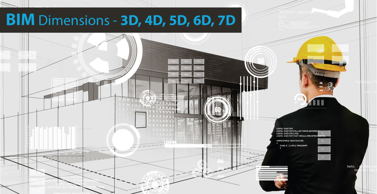
BIM has revolutionized the construction industry, offering a holistic approach to project management. In this article, we delve into the captivating realms of 3D, 4D, 5D, 6D, and 7D BIM. With BIM dimensions, architects, engineers, and contractors can unlock unparalleled insights and efficiencies throughout the entire project lifecycle.
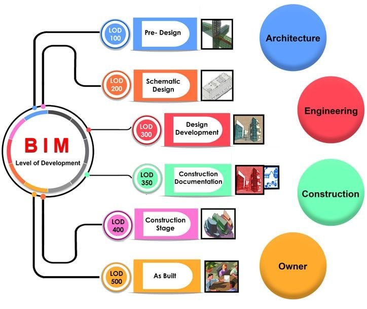
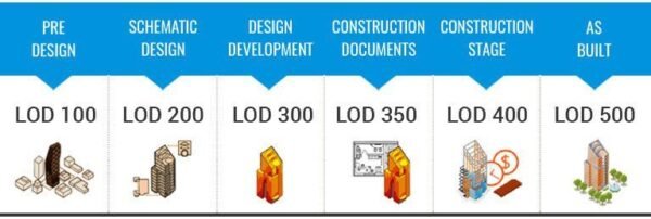
As a project progresses through different phases, the level of development in a BIM model also increases to different levels, including LOD 100, 200, 300, 350, 400, and 500. LOD is an industry-standard that defines various development stages of construction projects in BIM.
In this blog, we will explore the fascinating world of Building Information Modeling (BIM) and its dimensions! Join us as we unravel the innovative potential of BIM services, harnessing the power of virtual models, scheduling integration, cost estimation, sustainability analysis, and facility management. Discover how each dimension elevates project coordination and amplifies success. Get ready to embark on a remarkable journey through the multidimensional landscape of BIM!
What is meant by BIM?
BIM, short for Building Information Modeling, is a digital process that allows the creation and management of comprehensive 3D models of buildings and infrastructure projects. These models, known as BIM models, are rich in data and provide a collaborative platform for architects, engineers, contractors, and other stakeholders to work together effectively.
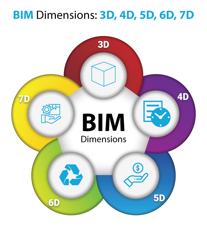
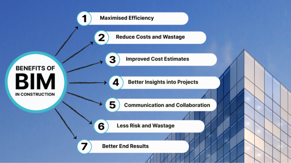
BIM dimensions refer to different aspects or levels of information that can be incorporated into the BIM models. Each dimension represents a specific type of data that enhances project management and decision-making throughout the project lifecycle. The types of BIM dimensions are:
3D BIM: Represents the spatial representation of the physical elements of a building or infrastructure project.
4D BIM: Adds the dimension of time to the 3D model, incorporating scheduling and sequencing information.
5D BIM: Combines the 3D model with cost data, allowing for accurate cost estimation and budgeting.
6D BIM: Includes sustainability and energy analysis, enabling the evaluation of environmental performance.
7D BIM: Integrates facility management information, such as operation and maintenance manuals, warranties, and asset management data.
8D BIM: Enhances safety management by integrating risk assessments and hazard mitigation into the model.
By incorporating these BIM dimensions into projects, BIM services can greatly enhance collaboration, efficiency, and decision-making throughout the entire lifecycle of a building or infrastructure project.
Unleashing the Power of BIM Services: Transforming Construction through Enhanced Collaboration and Efficiency
In the fast-paced world of construction, embracing Building Information Modeling (BIM) services has become paramount for success. BIM services offer a comprehensive suite of tools and techniques that revolutionize project management, design, and coordination. By harnessing the power of BIM dimensions, architects, engineers, contractors, and stakeholders can unlock a multitude of benefits throughout the project lifecycle.
3D Modeling and Visualization: BIM services provide sophisticated 3D modeling capabilities, enabling stakeholders to visualize the project in a virtual environment. This enhances design exploration, clash detection, and spatial coordination, resulting in reduced errors and rework.
Clash Detection and Coordination: With BIM services, clashes between different building components can be identified and resolved early in the design phase. This streamlines the construction process, minimizes delays, and improves overall project coordination.
Quantity Take-off and Estimation: BIM services enable accurate quantity take-off and cost estimation. By integrating 3D models with cost data, stakeholders can generate detailed quantity reports and make informed decisions regarding project budgets and resource allocation.
Construction Sequencing (4D BIM): BIM services incorporate the dimension of time, allowing for 4D visualization and construction sequencing. This facilitates effective project scheduling, resource allocation, and project phasing, ensuring efficient project execution.
Sustainability and Energy Analysis (5D BIM): BIM services include sustainability analysis tools that assess the environmental impact and energy performance of a building. This empowers stakeholders to make informed decisions regarding materials, systems, and energy-efficient strategies.
Facility Management Integration (7D BIM): BIM services extend beyond construction and into the operational phase of a building. Facility management integration enables the seamless transfer of asset data, maintenance schedules, and warranties, supporting efficient facility management and maintenance.
By embracing BIM services, the construction industry can embrace enhanced collaboration, streamlined workflows, and improved project outcomes. The integration of BIM dimensions empowers stakeholders to make data-driven decisions, reduce costs, minimize errors, and deliver projects with unmatched efficiency and sustainability. The future of construction lies in the transformative potential of BIM services, where virtual models seamlessly bridge the gap between concept and reality.
Breaking Ground with 3D BIM: Unveiling the Third Dimension of Construction Excellence
3D BIM, the third dimension of Building Information Modeling (BIM), revolutionizes the construction industry by providing a spatial representation of building elements in a virtual environment. It encompasses the creation of accurate and detailed 3D models that serve as a foundation for enhanced collaboration, visualization, and coordination among project stakeholders.
The benefits of 3D BIM are profound and extend across the entire project lifecycle:
Enhanced Visualization: 3D BIM allows stakeholders to visualize the project in a virtual space, providing a realistic representation of the building’s form, structure, and spatial relationships. This visual clarity fosters better communication, improved design exploration, and informed decision-making.
Clash Detection and Coordination: With 3D BIM, clashes and conflicts between different building elements can be identified and resolved before construction begins. This early clash detection minimizes costly on-site conflicts, reduces rework, and improves overall project coordination.
Improved Design Communication: 3D BIM models serve as powerful communication tools, enabling stakeholders to easily convey design intent and concepts to clients, contractors, and regulatory authorities. This facilitates a shared understanding of the project, leading to fewer misunderstandings and improved project outcomes.
Efficient Space Utilization:3D BIM models allow for optimized space planning and utilization. Designers can explore different spatial arrangements, evaluate functionality, and make informed decisions regarding spatial requirements, circulation paths, and room layouts, resulting in efficient and functional building designs.
Accurate Quantity Take-off: 3D BIM models provide the foundation for accurate quantity take-off, enabling stakeholders to generate detailed material and quantity reports. This streamlines the estimation process, improves cost control, and supports effective procurement and resource allocation.
Improved Stakeholder Collaboration: 3D BIM fosters collaboration among project stakeholders by providing a centralized and accessible platform for sharing information, design changes, and project updates. This promotes transparency, reduces coordination errors, and enhances teamwork throughout the project lifecycle.
With the advent of 3D BIM, the construction industry has witnessed a paradigm shift towards more efficient, accurate, and collaborative project delivery. By embracing the third dimension of BIM, stakeholders can navigate the complexities of construction with ease, visualize designs in unprecedented detail, and lay the groundwork for successful project outcomes. The future of BIM in construction lies in the immersive power of 3D BIM, where virtual models bring projects to life and pave the way for construction excellence.
Empowering Construction Schedules with 4D BIM: Unleashing the Fourth Dimension of Project Success
4D BIM, also known as the fourth dimension of Building Information Modeling (BIM), introduces the element of time into the digital modeling process. It combines the spatial representation of 3D BIM with the scheduling and sequencing information of construction activities. By incorporating the fourth dimension, 4D BIM revolutionizes project management and brings a multitude of benefits to construction projects.
The benefits of 4D BIM are significant and impact various aspects of the project lifecycle:
Visualizing Construction Sequences: 4D BIM enables stakeholders to visualize the construction sequence in a dynamic and interactive manner. This visual representation of activities and their dependencies allows for a clear understanding of the project timeline, aiding in project planning and coordination.
Optimized Construction Schedules: With 4D BIM, project schedules can be accurately integrated into the model. This integration facilitates the identification of potential clashes or delays, enabling stakeholders to make informed decisions and optimize the construction schedule for improved efficiency and productivity.
Early Clash Detection and Conflict Resolution: By overlaying construction sequences onto the 3D model, 4D BIM helps identify clashes and conflicts between different activities, trades, or resources. Early clash detection allows for proactive conflict resolution, reducing costly on-site rework and delays.
Resource and Equipment Management: 4D BIM provides a comprehensive overview of resource allocation, enabling stakeholders to effectively manage equipment, materials, and labour throughout the construction process. This improves resource utilization, minimizes downtime, and enhances productivity.
Communication and Stakeholder Engagement: The visual representation of construction sequences in 4D BIM facilitates effective communication and stakeholder engagement. It helps convey the project timeline, milestones, and progress to clients, contractors, and project teams, fostering collaboration and understanding.
Improved Project Control and Decision-making: 4D BIM enhances project control by allowing stakeholders to monitor project progress, identify potential delays, and analyze the impact of schedule changes. This empowers informed decision-making, enabling proactive measures to mitigate risks and ensure project success.
With the integration of the fourth dimension, 4D BIM brings a new level of insight and control to construction projects. It enhances visualization, streamlines scheduling, improves coordination, and empowers stakeholders to make informed decisions throughout the project lifecycle. By embracing 4D BIM, the construction industry is propelled into a new era of efficient and effective project management, where time becomes an integral component of digital modeling and construction success.
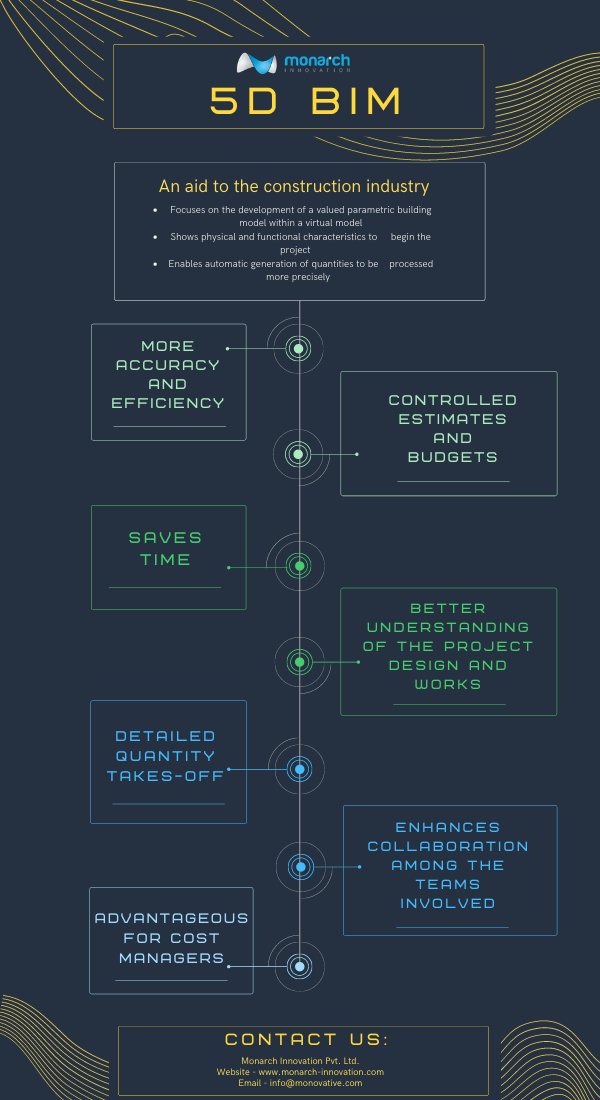
Unleashing Cost Efficiency with 5D BIM: Expanding the Boundaries of Project Estimation and Control
5D BIM, the fifth dimension of Building Information Modeling (BIM), introduces the element of cost into the digital modeling process. By integrating cost data with the spatial and temporal aspects of 3D and 4D BIM, 5D BIM enables accurate cost estimation, budgeting, and control throughout the entire project lifecycle. This innovative approach brings a multitude of benefits to construction projects.
The benefits of 5D BIM are transformative, impacting project management and cost control:
Accurate Cost Estimation:5D BIM allows stakeholders to generate accurate cost estimates by associating cost data with individual components within the 3D model. This level of detail improves cost accuracy, mitigates budget overruns, and facilitates informed decision-making.
Real-Time Cost Analysis: With 5D BIM, project stakeholders can perform real-time cost analysis throughout the project lifecycle. This empowers them to evaluate the cost impact of design changes, material substitutions, and scheduling adjustments, enabling proactive cost control and risk management.
Quantity Take-off Optimization: 5D BIM streamlines the process of quantity take-off by automating the extraction of quantities from the 3D model. This reduces manual effort, minimizes errors, and expedites the estimation process, leading to increased efficiency and productivity.
Improved Cost Control and Reporting: The integration of cost data within the BIM model facilitates continuous cost monitoring and control. It enables stakeholders to track actual costs against budgets, generate accurate reports, and make timely adjustments to ensure project financial success.
Enhanced Value Engineering: 5D BIM facilitates value engineering by providing insights into cost implications during the design phase. This enables stakeholders to explore cost-saving alternatives, optimize material usage, and identify opportunities for value enhancement, resulting in cost-effective and sustainable designs.
Stakeholder Collaboration and Transparency: 5D BIM promotes collaboration and transparency among project stakeholders. By visualizing cost data within the model, it fosters a shared understanding of project finances, aligns expectations, and enables better collaboration between owners, designers, contractors, and cost consultants.
With the integration of cost data, 5D BIM empowers stakeholders to make informed decisions, enhance cost control, and maximize project value. It revolutionizes the estimation process, improves cost visibility, and supports efficient budget management throughout the project lifecycle. By embracing 5D BIM, the construction industry can embark on a new era of cost efficiency, where accurate cost estimation and control become integral components of digital modeling and project success.
Revolutionizing Construction Management: Unleashing the Power of 6D BIM.
In the realm of construction management, the advent of Building Information Modeling (BIM) has transformed the way projects are planned, designed, and executed. One notable advancement in this field is the emergence of 6D BIM, an innovative approach that goes beyond traditional 3D modeling and incorporates the dimension of time and cost. By integrating project scheduling and cost data with the digital model, 6D BIM revolutionizes construction management, offering a comprehensive and dynamic platform for enhanced decision-making and project control.
Benefits of 6D BIM:
Enhanced Project Visualization: 6D BIM provides a comprehensive digital representation of the project, allowing stakeholders to visualize the entire lifecycle of the construction project. This includes construction sequencing, maintenance activities, and future renovations, facilitating better understanding and collaboration among team members.
Improved Time and Cost Management: By incorporating scheduling and cost data, 6D BIM enables accurate estimation and forecasting throughout the project lifecycle. This helps identify potential issues, optimize resource allocation, and enhance project planning, ultimately leading to improved time and cost management.
Enhanced Sustainability and Energy Efficiency: 6D BIM empowers project teams to assess the environmental impact and energy performance of a building throughout its lifecycle. By simulating and analyzing energy consumption, carbon emissions, and operational costs, stakeholders can make informed decisions to optimize sustainability and energy efficiency, ensuring long-term environmental benefits.
Streamlined Facility Management: With 6D BIM, facility managers can access a wealth of information about the building, including maintenance schedules, equipment specifications, and operating manuals. This centralized database streamlines facility management tasks, reducing maintenance costs, improving operational efficiency, and extending the lifespan of the asset.
Mitigated Risks and Enhanced Safety: 6D BIM allows for virtual simulations and clash detections, enabling the identification and resolution of potential clashes and conflicts before construction begins. This minimizes on-site risks, improves safety, and helps avoid costly rework, thereby enhancing overall project quality.
Transforming Construction Management: Unleashing the Potential of 7D BIM
Building Information Modeling (BIM) has revolutionized the construction industry, providing an advanced platform for design, planning, and project execution. Taking the capabilities of BIM even further, 7D BIM encompasses the dimensions of time, cost, and facility management. By integrating operational and maintenance data into the digital model, 7D BIM offers a comprehensive and dynamic approach to construction management, enabling improved decision-making, efficiency, and long-term value.
Benefits of 7D BIM:
Efficient Facility Operations and Maintenance: 7D BIM integrates comprehensive facility management data into the digital model, including equipment specifications, maintenance schedules, and asset lifecycle information. This enables facility managers to streamline operations, plan maintenance tasks, and optimize resource allocation, resulting in reduced downtime, enhanced performance, and cost savings.
Lifecycle Cost Analysis: By incorporating cost data throughout the entire lifecycle of a project, 7D BIM enables accurate cost estimation, forecasting, and analysis. Stakeholders can assess the financial implications of design decisions, material choices, and maintenance strategies, leading to improved cost control and budget management.
Improved Asset Performance and Longevity: With 7D BIM, project teams can monitor and analyze the performance of building systems and components throughout their operational lifespan. This allows for proactive maintenance, early detection of issues, and the optimization of asset performance, resulting in extended asset longevity and enhanced value.
Enhanced Sustainability and Energy Efficiency: 7D BIM empowers stakeholders to analyze and optimize the environmental impact and energy efficiency of a building over its lifecycle. By simulating energy consumption, conducting energy audits, and exploring sustainable design options, teams can make data-driven decisions that reduce carbon emissions, lower operational costs, and promote sustainable practices.
Seamless Collaboration and Communication: 7D BIM provides a central platform for collaboration among project stakeholders, facilitating effective communication and information exchange. Real-time access to accurate and up-to-date project information ensures transparency, minimizes errors, and improves coordination, leading to smoother project workflows and reduced rework.
The emergence of 7D BIM has elevated construction management to new heights by incorporating time, cost, and facility management dimensions into the digital model. The benefits of 7D BIM, including efficient facility operations, lifecycle cost analysis, improved asset performance, sustainability enhancements, and seamless collaboration, empower construction professionals to make informed decisions, optimize resources, and deliver projects with greater efficiency and long-term value. By embracing the power of 7D BIM, the construction industry can pave the way for more sustainable, cost-effective, and successful projects in the future.
Transforming Construction Safety and Efficiency: Unleashing the Power of 8D BIM
In the rapidly evolving world of construction, Building Information Modeling (BIM) has brought about significant advancements in project design, execution, and management. Among its many dimensions, 8D BIM stands out for its emphasis on safety and risk management. By embedding safety data into the BIM model, 8D BIM helps project teams anticipate risks, streamline communication, and enhance overall project efficiency.
This revolutionary dimension extends beyond the conventional benefits of BIM, such as 3D modeling, scheduling (4D), and cost management (5D). 8D BIM enables proactive safety planning and risk mitigation, resulting in safer worksites and optimized construction processes.
Benefits of 8D BIM:
Proactive Safety Planning and Hazard Mitigation: 8D BIM allows construction teams to integrate safety data directly into the digital model, enabling them to identify and address potential hazards before they arise on-site. From fall protection systems to fire safety protocols, 8D BIM ensures that risk management is embedded in every phase of the project.
Enhanced Project Efficiency through Real-Time Risk Management: With 8D BIM, safety measures are continuously updated as the project progresses, ensuring that real-time adjustments are made to mitigate new risks. This real-time monitoring enables project managers to handle unforeseen safety challenges quickly and efficiently.
Seamless Collaboration and Communication: 8D BIM promotes collaboration by serving as a central platform where all stakeholders—including architects, contractors, and safety managers—can access and share up-to-date safety information. This transparency ensures that everyone involved in the project remains aligned with the same safety protocols.
Cost Savings through Risk Reduction: Accidents on construction sites can result in costly delays, legal liabilities, and increased insurance premiums. By using 8D BIM to foresee and eliminate safety risks early, construction firms can avoid these expenses and save substantial amounts in the long term.
Regulatory Compliance and Reporting: 8D BIM ensures that safety regulations are fully integrated into the design and execution phases of the project. Compliance with local and international safety standards is made easier as safety protocols are automatically documented and traceable through the model.
8D BIM represents a groundbreaking approach to integrating safety management within construction processes, helping teams prevent accidents, reduce costs, and enhance collaboration. The proactive safety planning offered by 8D BIM goes beyond traditional methods, allowing construction projects to achieve higher levels of efficiency while keeping workers safe. By embracing the full potential of 8D BIM, construction firms can ensure safer, more cost-effective, and compliant project outcomes—ultimately leading to a more sustainable and efficient industry future.
Conclusion
Incorporating multiple dimensions into Building Information Modeling transforms it from a simple 3D design tool into a comprehensive project management system. Each additional dimension—whether it’s time (4D), cost (5D), sustainability (6D), facilities management (7D), or safety (8D)—adds more value to the project, helping stakeholders achieve greater efficiency, transparency, and control.
Monarch Innovation, with its expertise in BIM services, is at the forefront of this innovation, empowering construction professionals to unlock new levels of collaboration, decision-making, and project control. Embracing BIM dimensions is the key to a more streamlined, sustainable, and successful future in construction. Contact us for all your BIM Services requirements, we are happy to help.
MEP engineering encompasses the intricate planning, design, and management of Mechanical, Electrical, and Plumbing systems within buildings. These systems are the essential infrastructure that ensures the comfort, functionality, and efficiency of any structure. Mechanical systems regulate temperature and airflow, electrical systems provide power and lighting, while plumbing systems supply water and dispose of waste. MEP engineers work meticulously to integrate these systems seamlessly into the building’s architecture, considering factors like energy efficiency, sustainability, and compliance with building codes and regulations.
The Role of MEP Engineers
Roles like MEP engineering consultants play a pivotal role in the construction process, from conceptualization to completion. They collaborate closely with architects, structural engineers, and other stakeholders to develop holistic building design and drawings that meet the client’s requirements and objectives. By leveraging their expertise in mechanical, electrical, and plumbing systems, MEP engineers ensure that buildings are not only functional but also safe, reliable, and environmentally sustainable. Their responsibilities include system design, equipment selection, cost estimation, project management, and quality assurance.
Services Offered by MEP Engineering Firms
MEP engineering firms offer a comprehensive range of services to address the diverse needs of clients across various industries. These services encompass:
Mechanical Engineering: Designing HVAC systems, including heating, ventilation, and air conditioning, to maintain optimal indoor comfort and air quality.
Electrical Engineering: Planning and implementing electrical systems for power distribution, lighting, communication, and safety, ensuring reliable and efficient electrical infrastructure.
Plumbing Engineering: Developing water supply, drainage, and sewage systems, including fixtures, pipes, and pumps, to deliver clean water and manage wastewater effectively.
Additionally, MEP firms offer specialized services like energy management, sustainable design, commissioning, and building automation, enhancing building performance and sustainability.
The Benefits of Using MEP Services
Partnering with MEP Engineering Company offers numerous benefits for building owners, developers, and occupants alike. These benefits include:
Improved Energy Efficiency: MEP engineers employ innovative technologies and design strategies to minimise energy consumption and reduce operational costs over the building’s lifespan.
Enhanced Safety and Compliance: By adhering to building codes and regulations, MEP engineers ensure that building systems meet safety standards and regulatory requirements, mitigating risks and liabilities.
Cost Savings: Through efficient design, optimization of resources, and lifecycle analysis, MEP engineers help minimise construction costs and long-term operational expenses.
Optimal Performance: MEP engineers optimise building systems for performance, reliability, and resilience, ensuring seamless operation and minimal downtime.
Environmental Sustainability: By integrating sustainable design principles, renewable energy sources, and green building practices, MEP engineers contribute to reducing the environmental impact of buildings and promoting sustainability.
A Day in the Life of an MEP Engineer
The daily routine of an MEP engineer is dynamic and multifaceted, encompassing a wide range of tasks and responsibilities. A typical day may involve:
Collaborating with architects and other engineers to develop design concepts and project requirements.
Conducting site visits to assess existing conditions, coordinate with contractors, and inspect MEP installations.
Utilising computer-aided design (CAD) software to create detailed drawings, schematics, and specifications for MEP systems.
Performing calculations, simulations, and analyses to optimise system performance, efficiency, and cost-effectiveness.
Attending meetings with clients, contractors, and project teams to discuss progress, address challenges, and ensure project alignment.
Reviewing and approving shop drawings, submittals, and change orders to maintain project quality and compliance.
Throughout the project lifecycle, MEP engineers remain actively involved in all aspects of design, construction, and commissioning, leveraging their technical expertise and problem-solving skills to deliver successful outcomes.
How to Become an MEP Engineer
Becoming an MEP engineer requires a combination of education, training, certification, and practical experience. The typical path to becoming an MEP engineer includes:
Obtaining a bachelor’s degree in mechanical engineering, electrical engineering, or a related field from an accredited institution.
Gaining hands-on experience through internships, co-op programs, or entry-level positions in the engineering industry.
Pursuing professional licensure as a Professional Engineer (PE) or relevant certifications from recognized organisations such as the American Society of Heating, Refrigerating and Air-Conditioning Engineers (ASHRAE) or the National Fire Protection Association (NFPA).
Continuing education and professional development to stay current with industry trends, technologies, and regulations.
By continuously honing their skills and knowledge, aspiring MEP engineers can position themselves for rewarding careers in a dynamic and evolving field.
Choosing the Right MEP Engineering Partner
Selecting the right MEP engineering firm is crucial for the success of any construction project. When evaluating potential partners, consider the following factors:
Expertise and Experience: Look for firms with a proven track record of delivering high-quality MEP drawings and solutions across a range of project types and industries.
Technical Competence: Assess the firm’s technical capabilities, including proficiency in relevant software, tools, and methodologies for MEP design and analysis.
Collaboration and Communication: Choose a partner that values collaboration, open communication, and teamwork, fostering a positive and productive working relationship.
Sustainability and Innovation: Priorities firms that demonstrate a commitment to sustainability, green building practices, and innovation in MEP design and technology.
Reputation and References: Seek recommendations, reviews, and references from previous clients, contractors, and industry professionals to gauge the firm’s reputation and reliability.
By selecting an MEP engineering partner that aligns with your project goals, values, and expectations, you can ensure a smooth and successful collaboration from inception to completion.
Conclusion
MEP engineering stands as the cornerstone of modern building design, seamlessly integrating mechanical, electrical, and plumbing systems to foster safe, comfortable, and efficient environments. Monarch Innovation showcases the crucial role MEP engineers play in construction, designing sustainable buildings, optimizing energy performance, and ensuring regulatory compliance. Talk to our MEP Engineering Expert Today.
FAQs
Q: What does MEP stand for?
A: MEP stands for Mechanical, Electrical, and Plumbing engineering. It encompasses the design, installation, and maintenance of these systems in buildings.
Q:Why is MEP engineering important in construction?
A: MEP engineering ensures that buildings have functional heating, cooling, lighting, water supply, and drainage systems, enhancing occupant comfort and safety.
Q: What services do MEP firms typically provide?
A: MEP firms offer a range of services including system design, energy efficiency analysis, sustainability consulting, commissioning, and building automation solutions.
Q: What challenges do MEP engineers face in their work?
A: Challenges may include integrating complex systems, optimizing energy efficiency, managing project budgets and timelines, and addressing evolving technology and regulatory requirements.
Q: How can I find a reputable MEP engineering firm for my project?
A: Research online reviews, ask for referrals from colleagues or industry associations, and evaluate firms based on their experience, expertise, project portfolio, and commitment to sustainability.
Referred to as a lifecycle BIM tool, Level of Development (LOD) is a set of industry standards that provides the AEC industry the power to document, articulate, and specify the Building Information Modeling (BIM) contents properly and clearly. It defines the content (i.e., the geometric information, structured data, and linked documents) and the reliability of BIM elements at different development stages of the construction project.
Level of Development vs Level of Details
Level of Development is often misunderstood as the Level of Details, but both are different from each other. The level of Details signifies the proportion of details enclosed within the element of the model. Whereas Level of Development is the degree to which the specification and geometry of the elements and the information attached to it have been thought through, or it can be referred to as the degree to which the team members involved may depend on the information while using the model. It may be said that Level of Detail serves as an input to the element, whereas Level of Development is the output.
BIM Level of Development (LOD) 100, 200, 300, 350, 400 & 500
LOD 100
It is the pre-designing stage of LOD.
The LOD 100 element is a conceptual model where the parameters such as height, area, volume, orientation, and location are defined.
The information in this stage is considered as an approximation.
LOD 200
It is the schematic designing stage of LOD.
The LOD 200 element displays geometric features such as shapes, dimensions, locations, etc.
The level of complexity in LOD 200 is slightly more than that of LOD 100. It may also include some non-geometric information.
The information at this stage is also considered as an approximation.
The graphical representations of LOD 300 may be the same as the graphical representation of LOD 200, but what makes it different from LOD 200 is that the geometry and features at this stage are considered accurate.
The information at this stage can be used in the construction stage.
LOD 350
It is the construction documentation stage.
The information obtained in LOD 350 is the same as that obtained in LOD 300, but in this stage, the interfaces with other building components like connections and support are also included.
It indicates the way the component can be installed and the way it interacts with the systems of other buildings.
LOD 400
It is the construction stage of LOD.
It includes details such as fabrication, assembly, and installation of the components.
These details are of great use to the suppliers for manufacturing the components that are represented.
These are the fields that are verified in terms of shape, size, quantity, orientation, and location, which are considered to be accurate representations of the building elements post-construction.
These elements can be used as references for operation and maintenance by the facility managers.
LOD
Name
What It Shows
Detail Level
Typical Use
100
Concept
Basic representation of building volumes or site layout.
Very general, no specific details.
Early-stage planning and visualization.
200
Approximate
General geometry and location of elements with rough sizes.
Basic shape and size information.
Preliminary design and cost estimation.
300
Detailed
Accurate dimensions and detailed design of building components.
Detailed geometry and placement.
Detailed design, construction drawings.
350
Construction
Detailed design with construction details, including how components fit together.
High detail with construction specifics.
Construction documentation and assembly.
400
As-Built
Reflects the completed project with actual construction details.
Accurate to the built conditions.
Facility management and future modifications.
500
Operational
Includes operational data and performance information of the building.
Most detailed with operational data.
Long-term maintenance and operations.
Benefits of Level of Development (LOD)
The level of development is a vital element in the overall BIM process. Without it, the members working on a construction project may face difficulties working on the same page leading to inconsistencies that can damage the prospect of that project.
Improved Communication and Collaboration:- LOD makes communication and collaboration among the teams easier and faster. The LOD specification can be beneficial in the design process in the following ways:
Enhanced Design Process:- With standardized specifications and detailed information about all the elements, designers can deliver guidelines and data for people working downstream to ensure that there are no lapses in execution and maintenance.
Simplified Standardization for Contractors:- LOD makes defining a standard easier for contractors to take care of BIM execution. Simultaneously, design managers can explain the necessities at various levels of the design process to the teams with ease.
Accurate BIM Models:– LOD helps in making accurate BIM models. Concurrently, all the teams including the owners can specify accurately the level of detail they need from a BIM model and get clearance about the scope of the final BIM.
Conclusion
Understanding the Levels of Development (LOD) in BIM is essential for anyone involved in the architecture, engineering, or construction industries. From the early conceptual phases (LOD 100) to the as-built model (LOD 500), each stage provides a new level of detail and accuracy, guiding the project from start to finish. By utilizing the appropriate LOD, teams can ensure clear communication, better collaboration, and more successful project outcomes.
If you desire to have accurate and clash-free 3D models with Levels of Development stages from LOD 100 to 500 to enable the different construction teams involved in your construction project to articulate component geometry and information evolution, Monarch Innovation can be the right choice for you. It implements BIM projects for various construction tasks using Levels of Development from LOD 100 to 500 as per the needs and requirements. Contact Monarch Innovation to reduce your BIM risks with its LOD service.
FAQs
What is BIM Level of Development(LOD)?
BIM LOD, or Levels of Development, is a specification that defines the level of detail and accuracy of Building Information Modeling (BIM) elements at various stages of a construction project.
What are the different LOD levels in BIM?
There are six main LOD levels in BIM: LOD 100, 200, 300, 350, 400, and 500. Each level represents a different stage of development, ranging from conceptual design to as-built information.
What is the purpose of LOD in BIM?
LOD helps to communicate the reliability of information within a BIM model at different stages of a project. It ensures that all stakeholders have a clear understanding of the level of detail and accuracy in the model.
What are the key LOD levels, and how do they differ?
LOD 100: Conceptual design, approximate geometry. LOD 200: Schematic design, generalized elements. LOD 300: Detailed design, specific elements with accurate size and shape. LOD 400: Fabrication and assembly details, accurate in terms of size, shape, location, and orientation. LOD 500: As-built conditions, an exact representation of the as-built elements.
Why is LOD important in BIM?
LOD helps stakeholders understand the level of detail and reliability of information within a BIM model at different project stages. It sets expectations and ensures consistency in communication between project participants.
How can BIM LOD be implemented in a project?
BIM LOD can be implemented in a project by clearly defining the required level of detail and accuracy for each phase, establishing standards and guidelines, and using BIM authoring tools that support different LODs.
When it comes to interior design and construction, two terms that often come up are “millwork” and “casework.” While these terms may sound similar, they refer to distinct elements that play crucial roles in creating functional and aesthetically pleasing spaces. Understanding the key differences between millwork and casework is essential for anyone involved in the design or renovation process. In this blog post, we will delve into the nuances of Millwork construction and casework, exploring their definitions, purposes, and how they contribute to the overall look and feel of a space. Whether you’re a homeowner, architect, or design enthusiast, this guide will help you confidently navigate these concepts.
What is Millwork?
Millwork refers to the customized wooden architectural elements and finished carpentry found in interior spaces. It involves the precise crafting and installation of various woodwork components, such as moldings, trim, doors, cabinetry, and built-in furniture. Millwork is typically created by skilled artisans who use specialized tools and techniques to shape and manipulate wood into intricate designs. These crafted pieces are then installed in residential, commercial, and institutional settings to add both functionality and aesthetic appeal to the space. Millwork or millwork construction plays a significant role in enhancing the overall architectural style, character, and visual impact of a room, creating a sense of craftsmanship and refinement.
What is Casework?
Casework refers to installing pre-built cabinets, shelves, and storage units in interior spaces. Unlike millwork, which involves custom woodworking, casework involves the use of standardized modular components that are manufactured off-site and then assembled on-site. Casework offers versatility and efficiency, allowing for quick installation and customization options. It is commonly used in residential, commercial, and institutional settings to provide functional storage solutions and organization. From kitchen cabinets and bathroom vanities to office storage systems and retail display units, casework construction offers a wide range of design possibilities to optimize space utilization while maintaining a sleek and streamlined aesthetic.
Benefits: Millwork vs Casework
The choice between millwork and casework depends on the specific project requirements, budget, desired aesthetic, and timeline. Both options offer unique benefits that can enhance interior spaces in different ways.
Millwork Benefits:
Customization: Millwork allows for limitless customization options, as each piece is crafted according to specific millwork design requirements. Architectural millwork ensures a perfect fit and unique aesthetic appeal.
Architectural Character: Millwork adds architectural character and visual interest to interior spaces, creating a sense of craftsmanship and elegance.
Quality Craftsmanship: Millwork construction is often created by skilled artisans who pay meticulous attention to detail, resulting in high-quality and durable woodwork.
Flexibility: Millwork or Architectural millwork can be adapted to suit various architectural styles and several millwork design concepts, offering versatility in creating cohesive and personalized interiors.
Casework Benefits:
Efficiency: Casework is prefabricated off-site, allowing for faster installation and reduced construction time compared to custom millwork.
Cost-Effective: Casework is typically less expensive than millwork since it utilizes standardized modular components, making it a budget-friendly option.
Consistency: Casework ensures consistent quality and dimensions since it is manufactured using precise production methods and machinery.
Versatility: Casework construction offers a wide range of storage and organizational solutions, making it ideal for both residential and commercial applications where functionality is key.
Application: Millwork v/s Casework
Discover the diverse uses of millwork and casework construction, and how they enhance the functionality and aesthetics of interior spaces in distinct yet complementary ways.
Millwork Applications:
Millwork design is often employed to create intricate moldings, such as crown moldings, baseboards, and chair rails. These elements add a touch of elegance and sophistication to walls and ceilings. Millwork construction is ideal for crafting custom cabinetry and built-in storage solutions. From kitchen cabinets and bathroom vanities to bookshelves and entertainment centers, architectural millwork enhances functionality while providing a seamless and stylish integration with the overall design. Architectural millwork extends to the creation of custom doors and windows. These meticulously crafted elements not only serve their functional purposes but also contribute to the overall aesthetic appeal of a space. Also, these can be utilized to design and construct paneling and wainscoting, adding texture, depth, and visual interest to walls.
Casework Applications:
Casework construction finds widespread use in commercial spaces such as offices, retail stores, and hospitality venues. It involves the installation of modular cabinetry, display cases, and storage units to optimize organization and functionality. Casework is commonly employed in educational institutions to provide storage solutions in classrooms, laboratories, and libraries. It offers durability and flexibility, allowing for easy reconfiguration as per changing needs. Casework is used extensively in healthcare facilities for storage, shelving, and built-in cabinetry solutions in patient rooms, laboratories, and administrative areas. Casework construction also offers practical storage solutions in residential settings, including closets, laundry rooms, and garages. Modular cabinets and shelves provide organization and maximize space utilization.
Costing: Millwork vs. Casework – Comparing Financial Considerations
When it comes to cost, there are significant differences between millwork and casework in interior design projects. Millwork, being custom-made, tends to have a higher price tag due to the craftsmanship and customization involved. The materials, intricate detailing, and skilled labor contribute to Millwork construction’s elevated cost. On the other hand, casework offers a more budget-friendly option as it utilizes standardized modular components, reducing manufacturing and installation expenses. Casework’s cost-effective nature makes it a popular choice for projects with limited budgets or when time constraints are a factor. Ultimately, the decision between millwork and casework relies on the project’s financial resources and the desired level of customization and quality.
Which is preferable? Millwork v/s Casework
The preference between millwork and casework ultimately depends on the specific needs and priorities of a project. Millwork is favored when customization, craftsmanship, and a high-end aesthetic are of utmost importance. It offers limitless design possibilities, architectural character, and an unparalleled level of attention to detail. On the other hand, casework is preferred for its cost-effectiveness, efficiency, and versatility. It provides standardized storage solutions, and quick installation, and is well-suited for projects with limited budgets or tight timelines. Ultimately, the choice between Architectural millwork and casework is subjective and should be based on the project’s requirements, design vision, budget, and desired level of customization.
In conclusion,
Both millwork and casework have their unique advantages in interior design. Millwork offers custom craftsmanship and exquisite detailing, while casework provides cost-effective modular solutions. The decision between the two depends on factors such as budget, timeline, and desired level of customization. Ultimately, it’s about finding the right balance between aesthetic appeal, functionality, and financial considerations to create stunning and functional spaces.
In product development, two different approaches are commonly used: forward engineering and reverse engineering. While forward engineering involves creating new products from scratch, reverse engineering involves analyzing and replicating existing products. This blog will explore the key differences between forward engineering and reverse engineering, and the various applications of both approaches.
Forward engineering and reverse engineering are two different approaches used in product development. While forward engineering involves creating new products from scratch, reverse engineering involves analyzing and replicating existing products. Each approach has its advantages and disadvantages, and the decision to use one or the other depends on the specific needs of a project. Now, we will explore the key differences between forward engineering and reverse engineering in more detail.
Forward Engineering
Forward engineering is the traditional approach to product development, in which designers and engineers start with a concept or idea and work through a series of steps to create a final product. This process typically involves several stages, including ideation, prototyping, testing, and refinement. In forward engineering, the design and development process starts with a clear understanding of the requirements and specifications of the product. Designers and engineers then work together to develop a detailed plan for the product, which includes defining the materials, manufacturing processes, and assembly procedures that will be used.
Once the plan is in place, the product is then prototyped and tested to ensure that it meets all the necessary requirements. Feedback from testing is used to refine the design and improve the product until it is ready for production. Forward engineering is commonly used in product development for a wide range of industries, including manufacturing, electronics, and software. The key advantage of forward engineering is that it allows designers and engineers to create products that are customized to meet specific requirements and to optimize the design for the intended purpose.
Reverse Engineering
Reverse engineering, on the other hand, involves the analysis and replication of existing products. This process is often used when there is a need to reproduce a product that is no longer available or to modify an existing product to improve its performance. Reverse engineering typically involves several stages, including disassembly, measurement, analysis, and replication. The first step in reverse engineering is to disassemble the product and analyze its components to understand how it was designed and manufactured.
Once the product has been disassembled, measurements are taken of each component and its relationship to other parts of the product. This information is then used to create a 3D model of the product, which can be used to create new designs or modify the existing product. Reverse engineering is commonly used in industries such as aerospace, automotive, and manufacturing. The key advantage of reverse engineering is that it allows designers and engineers to understand the intricacies of an existing product and to make improvements or modifications based on that knowledge.
Comparison
The main difference between forward engineering and reverse engineering is the starting point of the design process. In forward engineering, the design process starts with a concept or idea and moves towards a finished product, while in reverse engineering, the process starts with a finished product and moves towards a new design.
Another key difference between forward engineering and reverse engineering is the level of control that designers and engineers have over the design process. In forward engineering, designers and engineers have complete control over the design and development of the product, while in reverse engineering, the design process is limited by the existing product.
Finally, the level of uncertainty is also a key difference between forward engineering and reverse engineering. In forward engineering, there is typically a higher level of uncertainty, as designers and engineers are working with a new concept or idea. In reverse engineering, there is less uncertainty, as designers and engineers are working with an existing product that has already been proven to work.
Difference between Forward Engineering and Reverse Engineering.
Key Points
Forward Engineering
Reverse Engineering
Definition
Forward Engineering is the process of creating a new system from scratch.
Reverse Engineering is the process of analyzing an existing system to understand its design and functionality.
Starting Point
Forward Engineering begins with requirements analysis, i.e., identifying the needs and expectations of stakeholders for the system.
Reverse Engineering begins with the analysis of an existing system to understand its design and functionality.
Output
Forward Engineering produces a new system that meets the specified requirements.
Reverse Engineering produces a system model that describes the existing system.
Decision Making
In Forward Engineering, design decisions are made upfront based on the requirements and objectives of the system.
In Reverse Engineering, decisions are made after analyzing the existing system to determine how it works and what changes may be necessary.
Focus
Forward Engineering focuses on creating a new system that meets future requirements and addresses identified needs.
Reverse Engineering focuses on understanding and analyzing an existing system to determine how it works and what changes may be necessary.
Approach
Forward Engineering follows a structured approach, involving the identification of requirements, system design, implementation, testing, and validation.
Reverse Engineering may follow an ad-hoc approach, where the analyst determines the best course of action based on the information available.
Level of Detail
Forward Engineering involves high-level abstraction, focusing on the overall system design and functionality.
Reverse Engineering involves low-level details, focusing on the specific components and mechanisms of the existing system.
Testing and Validation
In Forward Engineering, testing, and validation are essential to ensure that the new system meets the specified requirements and works as intended.
In Reverse Engineering, testing and validation may be necessary to confirm the accuracy of the system model and identify any discrepancies or inconsistencies.
Examples
Examples of Forward Engineering include software development, building a bridge, or designing a new product.
Examples of Reverse Engineering include analyzing malware to understand its behavior and reverse engineering a competitor’s product to understand its design and functionality.
Types of Reverse Engineering and Forward engineering
There are several types of reverse engineering and forward engineering methods used in various industries for product development. Let’s look at some of the most common types:
Types of Reverse Engineering:
3D Scanning: This method involves using a 3D scanner to create a digital model of an existing object. The scanner captures the object’s geometry and creates a 3D point cloud that can be used to create a CAD model.
Photogrammetry: Photogrammetry is a technique that uses photographs to create a 3D model. This method involves taking multiple photographs of an object from different angles and then using software to create a 3D model from the images.
CT Scanning: CT scanning is a method that uses X-rays to create a 3D image of an object’s internal structure. This method is often used in the medical industry to create detailed images of bones and other internal structures.
Types of Forward Engineering:
Conceptual Design: This involves the creation of initial concepts and sketches to define the overall design of a product.
Detailed Design: Once the conceptual design is approved, detailed design work begins. This involves creating detailed drawings, specifications, and engineering documents that provide all the information needed to manufacture the product.
Prototyping: Prototyping involves creating a physical model of the product to test its functionality and design. This stage may involve multiple iterations until a final prototype is approved for production.
Manufacturing: Once the design and prototype are finalized, the manufacturing process begins. This involves producing the product on a larger scale, typically using specialized equipment and processes.
It’s important to note that reverse engineering and forward engineering are often used in conjunction with each other. For example, a product may be reverse-engineered to create a digital model, which is then used in the forward engineering process to refine the design and create a final product.
In conclusion,
Both forward engineering and reverse engineering have their unique roles in the product development process. Forward engineering helps in creating new products from scratch, while reverse engineering assists in improving existing products by analyzing and reproducing them. At Monarch Innovation, we understand the importance of both types of engineering in product development and offer services in both areas, including 3D reverse engineering and forward engineering for industrial product design. Our team of experts provides innovative and effective solutions to meet our client’s needs, whether it is to create a new product or improve an existing one. Contact us to learn more about how we can help you with your product development needs.
CAD (Computer-Aided Design) drafting service is an essential part of many industries, including architecture, engineering, construction, and manufacturing. CAD drafting involves the creation of technical drawings and plans using specialized software on a computer. The general characteristics of CAD drafting service include the use of precise and accurate drawings that guide the fabrication or construction process, as well as the ability to easily edit and modify drawings as needed. Key characteristics of a CAD drafting service include the use of industry-specific software and tools, as well as the expertise and experience of professional drafters who are skilled in creating accurate and detailed technical drawings. CAD drafting services can be outsourced to third-party providers, allowing businesses to leverage specialized expertise and resources to improve their operations and bottom line.
What are fabricators and how is CAD drafting service beneficial for them?
Fabricators are businesses that specialize in the manufacturing and assembly of metal, plastic, and other materials into finished products, such as machine parts, industrial equipment, and consumer goods. These businesses rely on CAD (Computer-Aided Design) drafting services to create precise and accurate technical drawings and plans that guide the fabrication process.
Some key reasons why CAD drafting is important for fabricators include:
Precision and Accuracy: CAD drafting services enable fabricators to structure fabrication drawing with precision and accuracy which ensure the finished products meet the required specifications and standards.
Faster Turnaround Time: CAD drafting allows fabricators to create technical drawings and plans more quickly and efficiently, speeding up the fabrication drawings production process and reducing lead times.
Improved Quality Control: CAD services enable fabricators to catch errors and inconsistencies in the design phase, before the product is fabricated, reducing the risk of costly mistakes.
Better Collaboration: CAD drafting services make it easier for fabricators to collaborate with clients, engineers, and other stakeholders by providing a visual representation of the product, allowing for more efficient communication and collaboration.
Overall, CAD services are an essential tool for fabricators, helping to ensure that the finished product meets the required specifications and standards, while also improving efficiency, productivity, and collaboration.
What are the different types of CAD drafting Services?
CAD drafting services offer fabricators a range of options for creating precise technical drawings and plans that guide the fabrication process. Here are some categorizations of CAD drafting services for fabricators:
2D Fabrication Drawings: 2D fabrication drawings are two-dimensional technical drawings that provide detailed information on the dimensions, materials, and specifications of a product. These drawings are often used to guide the fabrication process, as they provide a clear and detailed representation of the finished product. 2D fabrication drawings are essential for fabricators, as they ensure that the product is fabricated to the correct specifications and standards.
3D Modelling:3D modelling is a CAD drafting service that allows fabricators to create three-dimensional representations of products, allowing for a more realistic and detailed view of the finished product. 3D modeling is useful for fabricators, as it enables them to visualize and test the product before it is fabricated, reducing the risk of errors and inconsistencies.
Assembly and Detailing: Assembly and detailing is a CAD drafting service that provides detailed information on how the product should be assembled, including the location and orientation of each component. These drawings are essential for fabricators, as they ensure that the product is assembled correctly and efficiently.
Prototyping: Prototyping is a CAD drafting service that involves the creation of a physical model or prototype of the product, allowing for a more realistic and detailed representation of the finished product. Prototyping is important for fabricators, as it enables them to test the product and make any necessary changes before it is fabricated, reducing the risk of errors and inconsistencies.
What are some of the most important CAD drafting software for different types of fabricators?
Some of the most important CAD drafting software and tools for fabricators include:
AutoCAD: AutoCAD is a popular CAD drafting software used by fabricators for creating detailed 2D and 3D drawings. AutoCAD is known for its precision and accuracy, as well as its ability to work with a variety of file formats.
SolidWorks: SolidWorks is a 3D modelling software used by fabricators for designing complex parts and assemblies. SolidWorks is known for its advanced features and ability to handle complex geometries, making it a valuable tool for fabricators.
Inventor: Inventor is another 3D modelling software used by fabricators, particularly in the metal fabrication industry. Inventor is known for its ability to handle large assemblies and complex geometries, as well as its integration with other Autodesk software.
Tekla Structures: Tekla Structures is a 3D modelling software specifically designed for the construction industry. Tekla Structures is known for its ability to handle large and complex structures, as well as its advanced detailing and fabrication capabilities.
Revit: Revit is a Building Information Modelling (BIM) software used in the construction industry for creating detailed building models. Revit is known for its ability to handle large and complex building designs, as well as its advanced collaboration and coordination features.
CAM Software: CAM software, such as Mastercam or Fusion 360, is used in the manufacturing industry to create detailed machining plans and toolpaths for CNC machines. CAM software is essential for fabricators, as it enables them to produce complex parts and assemblies with high accuracy and efficiency.
How to choose the best CAD drafting service source?
Here are some steps to follow when selecting a CAD drafting service:
Determine Your Specific Needs: Before selecting a CAD drafting service, it’s important to determine your specific needs and requirements. Consider factors such as the size and complexity of the project, the required level of detail, and the desired turnaround time.
Research Potential Providers: Once you have determined your specific needs, research potential CAD drafting service providers. Look for providers with experience in your industry and a track record of delivering high-quality work on time and within budget.
Check for Industry-Specific Knowledge: Make sure the provider you choose knows the specific industry you operate in, such as metal fabrication, plastics manufacturing, or construction.
Evaluate the Provider’s Tools and Software: The CAD drafting service provider should be equipped with the latest software and tools and should be able to work with a variety of file formats.
Assess Quality of Work: Request samples of the provider’s previous work and evaluate their quality. Look for drawings that are precise, accurate, and visually appealing.
Review Turnaround Time: Make sure the provider can deliver the finished drawings within your desired timeframe. Consider factors such as the provider’s workload, availability, and any potential delays.
Check Pricing: Finally, consider the provider’s pricing and make sure it fits within your budget. Compare pricing across multiple providers to ensure you are getting a fair price for the quality of work you require.
A real-life example showcasing how structural steel fabrication drawings help the fabricator
Structural steel drawings created using CAD software can help fabricators improve their processes and operations in several ways. Here is a real-life example of how CAD drafting services can benefit a fabricator:
A fabricator specializing in structural steel fabrication needed to produce a set of detailed drawings for a complex project that involved fabricating and installing steel beams and columns for a large commercial building. The fabricator engaged a CAD drafting service to create the fabrication drawings.
By using CAD software, the drafting service was able to create accurate and detailed 3D models of the steel beams and columns, as well as detailed fabrication drawings that included all the necessary information such as dimensions, material specifications, welding details, and assembly instructions.
The detailed fabrication drawings enabled the fabricator to:
Improve Accuracy: The detailed fabrication drawings created using CAD software ensured that all the parts were accurately sized, cut, and fabricated according to the design specifications, reducing the risk of errors and rework.
Increase Efficiency: By using detailed fabrication drawings, the fabricator was able to optimize their production processes, reducing the time and effort required to fabricate and install the steel beams and columns.
Enhance Safety: The detailed fabrication drawings ensured that all the parts were fabricated and installed according to the design specifications, improving the safety and stability of the building.
Reduce Costs: The accurate and detailed fabrication drawings enabled the fabricator to reduce waste and minimize the need for rework, ultimately reducing the overall cost of the project.
Conclusion
Choosing a CAD drafting service provider that specializes in the fabrication industry can provide numerous benefits, including expertise in industry-specific tools and software, an understanding of fabrication processes and requirements, and dedication to providing the best quality work on time and within budget. At the end of the day, the decision to outsource CAD drafting services ultimately comes down to what is best for your business. So, take the time to do your research, evaluate your options, and choose a CAD drafting service provider that can help you achieve your goals and take your business to the next level. If you are looking to improve your fabrication processes and deliver high-quality products and services to your clients, then outsourcing Monarch Innovation as a CAD drafting service provider is the right choice for you.
Building Information Modeling (BIM) has revolutionized the architecture, engineering, and construction industries in recent years, and its importance will only grow in 2023. With the ever-evolving technological landscape, BIM construction constantly evolves and introduces new trends that make the construction process more efficient, cost-effective, and sustainable.
This blog will discuss five innovative BIM trends expected to dominate the construction industry in 2023. These trends include the increased use of augmented reality, artificial intelligence, modular construction, digital twin technology, and 5D BIM. Let’s dive deeper into each direction and explore how they are set to transform the construction industry in the coming year.
What is BIM for future construction?
BIM, short for Building Information Modeling, is a digital technology used in the architecture, engineering, and construction industries. It involves creating a digital representation of a building or infrastructure project, which includes all the relevant information about its design, construction, and maintenance throughout its entire lifecycle.
BIM enables various stakeholders, such as architects, engineers, contractors, and owners, to collaborate and share information in real time, leading to a more collaborative and efficient construction process. BIM creates a 3D modelof the building, which can be further enriched with additional data such as materials, cost estimates, and construction schedules. BIM can also simulate the performance of the building, allowing for better decision-making and optimization of the design and construction process. Overall, BIM helps improve construction projects’ accuracy, quality, and sustainability while reducing costs and minimizing errors.
Benefits of BIM
BIM (Building Information Modeling) has numerous benefits for the architecture, engineering, and construction industries. Here are some of the main advantages of using BIM:
Improved collaboration: BIM facilitates better collaboration and stakeholder communication, reducing errors and misunderstandings. It allows for real-time sharing of information, enabling better decision-making.
Enhanced visualization: BIM creates a 3D model of the building or infrastructure project, making it easier to visualize the final product. It also allows for the simulation of various design scenarios, enabling stakeholders to make better decisions.
Cost and time savings: BIM can help reduce project costs and construction time by identifying potential problems in advance, optimizing the design, and reducing the need for rework.
Increased accuracy: BIM models are accurate and comprehensive, reducing errors and omissions in the design and construction process.
Sustainability: BIM can help optimize the building’s energy performance, reduce waste, and increase efficiency, making it more sustainable.
Overall, BIM is a powerful tool that helps to improve the quality, efficiency, and sustainability of construction projects while reducing costs and minimizing errors.
Usage of BIM in the Construction industry
BIM (Building Information Modeling) is increasingly used in the construction industry due to its many benefits. Here are some of how BIM is used in the construction industry:
Design and engineering: BIM is used to create accurate 3D models of buildings, allowing for better visualization and collaboration among designers and engineers.
Cost estimation: BIM models can be used to generate accurate cost estimates, which can help project owners and contractors to manage budgets more effectively.
Construction planning: BIM models can be used to plan construction schedules and optimize the construction process, reducing costs and time.
Project management: BIM can manage project data and documentation, making tracking changes and communicating with stakeholders easier.
Facility management: BIM models can manage building information throughout its entire lifecycle, making it easier to maintain and operate the building effectively.
Overall, BIM is a powerful tool that can be used to improve the quality, efficiency, and sustainability of construction projects while reducing costs and minimizing errors. Its usage will grow in the construction industry in the coming years.
How to use BIM effectively in the construction industry?
Building Information Modeling (BIM) is a digital representation of a building project that can be used to improve collaboration, productivity, and efficiency in the construction industry. Here are some ways to use BIM effectively:
Plan and design: BIM can be used to create detailed 3D models of buildings, which can be used to visualize the project and identify potential problems before construction begins. It can help to save time and reduce costs.
Collaborate: BIM allows all stakeholders, including architects, engineers, contractors, and owners, to collaborate on a single platform. It can help ensure everyone is on the same page and that changes are communicated effectively.
Cost estimation: BIM can estimate the construction cost by providing detailed information on the materials, labor, and equipment required for the project. It can help to ensure that the project is completed within budget.
Construction management: BIM can manage the construction process by tracking progress, scheduling tasks, and identifying potential issues. It can help ensure the project is completed on time and to the required quality standards.
Facilities management: BIM can manage the building after construction is complete by providing detailed information on the building’s systems and components. It can help to ensure that maintenance and repairs are carried out efficiently.
It is essential to have a clear implementation plan and ensure all stakeholders are trained on its use-to-use BIM effectively. Additionally, it is vital to use suitable BIM software for the project and ensure that data is entered accurately and consistently.
BIM Trends in 2023
Based on current industry trends and advancements in technology, here are five potential BIM trends that may emerge in 2023:
Integration with artificial intelligence (AI): AI has the potential to greatly enhance BIM by automating repetitive tasks, such as clash detection and material selection, and providing insights based on data analysis. In 2023, we may see more BIM software incorporating AI capabilities to improve efficiency and accuracy.
Increased adoption of modular construction: Modular construction, where buildings are constructed offsite in modules and assembled on-site, is becoming more popular due to its efficiency and cost-effectiveness. BIM can play a key role in modular construction by providing accurate and detailed models for prefabrication. In 2023, we may see more BIM tools and processes tailored to support modular construction.
Greater emphasis on data-driven decision-making:BIM software collects a vast amount of data, and in 2023, there may be an increased focus on using this data to make more informed decisions throughout the project lifecycle. This could include using data to optimize building performance, improve safety, and reduce costs.
More widespread use of mobile BIM: As mobile devices become more powerful and ubiquitous, there is an opportunity to use BIM models on-site through mobile applications. In 2023, we may see more BIM software developers creating mobile apps that allow for real-time access to BIM models and data.
The continued evolution of open BIM standards: Open BIM standards, such as Industry Foundation Classes (IFC) and Building SMART, are becoming more widely adopted, which helps to improve interoperability between different BIM software and systems. In 2023, we may see further evolution of these open standards to improve collaboration and data exchange across the construction industry.
Conclusion
Monarch Innovation is a company that specializes in providing BIM services and solutions to the construction industry. Monarch Innovation can help you to implement BIM on your construction projects by providing a clear plan and strategy for its adoption. They can also offer your team training to ensure they are proficient in using BIM software.
Monarch Innovation can help you leverage BIM’s power to enhance collaboration, productivity, and efficiency in your construction projects. Monarch Innovation can create detailed 3D models of your building projects using BIM software. These models can be used to identify potential problems and improve collaboration between stakeholders.
VDC is a process that uses advanced digital technologies to create a 3D virtual model of a building or infrastructure project, allowing stakeholders to simulate and analyse the project’s design, construction, and operation phases. The virtual design process helps reduce errors and rework, increases collaboration, and enhances communication among all project stakeholders, resulting in better project outcomes.
However, implementing VDC in the AEC industry can present several challenges, such as specialized software and hardware, training, and team collaboration. This blog will delve into the benefits, challenges, and strategies of implementing VDC in the AEC industry, providing valuable insights and recommendations for professionals in the field.
VDC Meaning
Virtual Design Construction (VDC) is a process that uses advanced digital technology to create virtual models of a building or infrastructure project. The process involves integrating building information modelling (BIM) and other 3D modelling software with construction project management software to create a virtual model that accurately represents the entire project.
VDC simulates the entire construction process from start to finish, allowing the project team to identify and resolve potential issues before they occur in the real world. This technology can help reduce costs, minimize errors, and waste, and improve project timelines by providing an accurate and realistic view of the project before construction begins.
VDC is beneficial in complex construction projects, such as high-rise buildings, bridges, and large-scale infrastructure projects, where coordinating multiple disciplines and systems is critical to success.
Virtual Design Construction (VDC) benefits
There are several benefits to using Virtual Design Construction (VDC) in construction projects. Below are the key benefits:
Improved collaboration: VDC allows project stakeholders to work virtually, enhancing communication and collaboration between architects, engineers, contractors, and owners.
Reduced errors and rework: By using VDC, potential design and construction issues can be identified early on, reducing errors, and the need for rework, saving time and money.
Increased efficiency: VDC allows for optimizing construction sequences, material usage, and scheduling, improving efficiency and productivity.
Enhanced project visualization: VDC provides a realistic and immersive visualization of the project, making it easier to understand and communicate complex ideas and concepts.
Improved cost management: VDC allows for accurate cost estimation, tracking, and control throughout the project lifecycle, reducing the risk of cost overruns.
Improved safety: VDC can help identify potential safety hazards before construction begins, reducing the risk of accidents and injuries.
Overall, virtual construction can help improve project outcomes, reduce risk, and increase project efficiency, ultimately leading to cost savings and improved quality.
Virtual Design Construction (VDC) challenges
While Virtual Design Construction (VDC) offers many benefits, several challenges must be addressed to implement this technology in construction projects effectively. Listed below are some of its challenges:
Integration: VDC requires integrating multiple technologies and software systems, which can be complex and time-consuming.
Training: VDC requires specialized training and expertise, which can be difficult to acquire and maintain.
Data management: VDC generates a large amount of data that must be managed and analyzed effectively to be valid.
Cost: VDC can be expensive to implement, requiring investment in hardware, software, and training.
Resistance to change: The adoption of VDC may be met with resistance from some stakeholders who may be hesitant to change established processes and workflows.
Limited interoperability: Some software tools used in VDC may not be compatible, making it difficult to share data and collaborate effectively.
Complexity: VDC is a complex technology requiring high coordination and collaboration between project stakeholders.
Overall, VDC presents significant challenges that must be carefully managed to ensure its successful implementation in construction projects. However, with proper planning and execution, the benefits of VDC can outweigh these challenges and lead to improved project outcomes.
What is Virtual Design Construction (VDC) for AEC?
Virtual Design Construction (VDC) for AEC refers to using advanced digital technologies and processes to create a virtual model of a building or infrastructure project before construction begins. VDC technology integrates building information modelling (BIM) and other 3D modelling software with construction project management software to create a virtual model that accurately represents the entire project.
In the AEC industry, VDC simulates the entire construction process from start to finish, allowing project teams to identify and resolve potential issues before they occur in the real world. VDC technology can help reduce costs, minimize errors, and waste, and improve project timelines by providing an accurate and realistic view of the project before construction begins.
VDC technology is particularly useful in complex construction projects, such as high-rise buildings, bridges, and large-scale infrastructure projects, where coordinating multiple disciplines and systems is critical to success. Using VDC technology, project teams can optimize construction sequences, material usage, and scheduling, improving efficiency and productivity.
Overall, VDC technology can help AEC industry stakeholders deliver better-quality projects on time and within budget while improving safety and reducing risk. It enables project teams to collaborate more effectively, communicate more clearly, and make more informed decisions throughout the project lifecycle.
Virtual Design Construction (VDC) Strategies for AEC
Here are some key strategies that can be implemented in the Architecture, Engineering, and Construction (AEC) industry to leverage Virtual Design Construction (VDC) technology effectively:
Plan early: Incorporate VDC planning early in the project lifecycle to establish project goals and ensure all stakeholders align on the project vision.
Collaboration and Communication: Encourage collaboration and communication among all project stakeholders to identify potential design and construction issues early on and work collaboratively to address them.
Standardization: Develop standardized processes and procedures for VDC implementation to ensure consistency across projects and reduce potential errors.
Training: Invest in VDC training and development to ensure all project team members have the necessary skills and knowledge to use VDC technology effectively.
Technology: Select the right software and hardware tools for the project needs and ensure that all devices are interoperable, scalable, and flexible.
Data Management: Implement effective data management processes to ensure that all data is collected, organized, and analyzed consistently and on time.
Continuous Improvement: Continuously evaluate the VDC implementation and processes to identify improvement opportunities and make necessary adjustments.
Implementing these strategies allows AEC industry stakeholders to leverage VDC technology to improve collaboration, efficiency, and project outcomes. Ultimately, VDC can help organizations deliver better-quality projects on time and within budget while enhancing safety and reducing risk.
Conclusion
Monarch Innovation can offer engineering consulting services to help companies determine their VDC needs and develop a comprehensive VDC implementation plan. Their team of experts can develop detailed 3D models of building or infrastructure projects, providing stakeholders with realistic and immersive visualization of the project before construction begins. They also offer training programs to educate project team members on using VDC technology, software, and best practices.
The star player in the construction sector right now is BIM. Although the technology has been around for nearly ten years, over the past two years, much excitement has been generated around BIM in the construction industry. Although everyone knows BIM stands for building information modelling, what exactly is BIM? The process of creating and managing a project’s physical and functional information is known as BIM.
The process results in BIMs, or building information models, essentially digital files that detail every component of the project and aid in decision-making throughout a project cycle. BIM is more complex than 3D modeling, despite popular misconceptions.
What is BIM?
Building information modeling (BIM) is the digital representation of a building’s structural and functional details. A BIM construction is a shared knowledge resource when used as a solid basis for decisions throughout a facility’s life cycle, which is defined as existing from the time of initial conceptualization through demolition.
Applications of Building Information Modeling
The following applications for a building information model are possible:
Visualization: Producing 3D modeling in-house is simple and requires little extra work.
Code reviews: These models may be used by fire departments and other authorities to examine construction projects.
Cost estimation: BIM software has options for cost estimation and process automation. Material quantities are automatically retrieved and updated when modifications are made to the model.
Sequence: Coordination of material ordering, manufacturing, and delivery dates for all building components is possible using a BIM construction.
Conflict, interference, and collision detection: All key systems may be promptly and automatically tested for conflicts since building information models are made to scale in 3D modeling. This procedure, for instance, can confirm that plumbing doesn’t cross paths with steel beams, ducts, or walls.
Fabrication: For various building systems, shop drawings can be easily produced. For instance, once the model is finished, the sheet metal ductwork shop drawings can be easily created.
Forensic analysis: Using a building information model, it is simple to graphically represent potential failures, leaks, evacuation routes, and other scenarios.
Facilities management: It can be utilized by facilities management departments for remodelling, space planning, and maintenance tasks.
BIM V/S Old Traditional Methods
BIM Construction gives project participants better control and precision from the onset, enabling them to handle aspects like cost, quality, and time more effectively. These kinds of advantages have a significant impact on every aspect of information management, including productivity and manufacturing efficiency. The use of BIM presents many potential challenges compared to the conventional approach.
Because of the explicit design of the information and its availability to all stakeholders, better information management, use, and sharing can enhance decision-making activities. Participants in projects were accustomed to using their tools and systems to transmit information that was organized and appropriate for their unique needs and demands in the early days of the advent of BIM.
BIM Construction (Usage in different stages of construction)
Pre – Construction Stage
All project appraisal during the pre-construction phase aims to predict potential financial gains for the client and the contractor. BIM is useful for providing a framework for evaluating the project’s viability and for assessing the building’s future performance in terms of regulations about functionality and constructability. Studies on energy, acoustics, and illumination are now being conducted and studied. They will eventually significantly impact the outcome if adequately examined. With the conventional method, performing this kind of sustainability analysis was impossible. Because design and construction shareholders are involved, the initial cost of using a BIM system is more incredible.
Construction Stage
BIM construction enables cost savings both during the actual construction phase and during the pre-construction stage. In reality, because of the cost reductions, it prevents and is quite alluring, especially for larger organizations. One advantage of BIM in this stage is the ability to inspect all project components in advance, manage and plan the building construction process, minimize the need for on-site inventory, and lower expenses. In addition, BIM can monitor the project’s progress by routinely updating the model with the installation dates of both structures and systems.
Post – Construction Stage
Important data was gathered and kept in the BIM construction system during the entire process, allowing easy access and documentation even after the construction. For facility managers, most issues and time-consuming tasks are the time spent gathering information. The BIM will handle this situation with ease. In reality, before making any structure improvements, such as renovations or maintenance, a direct person had to be contacted through on-site surveys, but this is no longer essential.
Advantage Of BIM
Many business processes can be supported and enhanced by BIM technology’s process automation. Even though the architecture, engineering, building, and facility management industries were among the first to adopt BIM, numerous advancements had previously been made. The disciplines of BIM construction are connected to BIM technology and the process is the focus of the construction design and building because they respond to the growing strain of higher complexity, faster development, greater sustainability, and reduced building costs and usage.
Future Potential
BIM is a reasonably new technology, particularly in the construction industry, which is notoriously sluggish in adopting new technologies. BIM supporters assert that it will soon provide a great deal of value in terms of the following:
Increasing visual clarity.
Increasing productivity by making it simple to find information.
Improving construction document coordination.
Linking crucial data, including vendors for specific materials, the location of information, and the quantity requirements for tenders.
Quickening the pace of deliveries.
Lowering overall expenses
Lastly,
Building information modeling (BIM) as a methodology has vast implications for the construction industry. Still, in the end, in our opinion, it all boils down to the various project parties being able to access and use all the data they require at each stage of the project without needless duplication of effort or time spent on repetitive work. It is necessary for the project’s partners to transfer data effectively and in a format that everyone can access and use at various stages.
To assist clients in re-engineering their manufacturing processes and improving organizational effectiveness and results, Monarch Innovation creates personalized solutions. Monarch Innovation has a competitive advantage in the sector because of its cutting-edge infrastructure and a staff of highly qualified experts. The two main principles that Monarch Innovation fosters are innovation and creativity!!
Looking to Hire BIM Services Company?
Get in Touch With Our Experts Here. We’ll Help You!
On existing site characteristics or brownfields, many AEC projects are located. More time, money, and effort are used on projects that start with an inspection and documentation of the circumstances on the job site. Even if BIM services can automate new construction work, how can it be used for existing building documentation?
High-resolution 3D modeling of current built and natural settings are captured using the scan to BIM method and transformed into usable models. The time-consuming and customary process of current site documentation can be automated using laser scanning technology.
The scanners are positioned in various locations to collect the physical forms on-site. The 3D modeling created from the scans, known as “Point Clouds,” is converted into architectural drawings. How exactly does this procedure operate? Learn more about the specifics in this article!
Scan to BIM (Major details)
Different technologies are used today to modernize and provide better customer service. A cutting-edge method called SCAN to BIM Design Build harnesses the strength of 3D modeling and laser tracking technology with building information modeling. Construction experts may successfully plan projects from the final assembly stage through the use of laser scan to BIM technology, cutting the project duration by between 40% and 90%. A single reference file in a precise digital model is provided by the scan to BIM services design-build solution, giving customers various benefits like:
Obtain Reliable Reference Data in Real Time
Manage, Benchmark, Synchronize, and Organize Incoming Data
Plan and improve the performance of new buildings
How does BIM relate to scan-to-BIM?
The need for BIM deployment and the production of BIM schematics for existing buildings is expanding within the AEC sector. Scan-to-BIM is rapidly turning into an essential step in the BIM process.
Before a designer even begins, reality capture of as-built drawings conditions can give the model the most important information when a project involves an existing structure or site, as it will in most cases.
Here is a straightforward summary: Scan-to-BIM uses laser scan data to digitally capture a physical place or site, which is then used to build, develop, and maintain a BIM model.
How Does Scan to BIM Process Work?
Four stages make up the complete Scan to BIM process:
Identification of information needs:
Before beginning the Scan to BIM process, it is crucial to identify all the information needs for the desired model and drawings. The amount of detail in your model must be determined because greater modeling accuracy increases the as-built BIM’s dependability for the intended application. However, the cost increases with the level of detail. Therefore, a trade-off between price and data density must be negotiated. We locate the following data at this stage:
Necessary building materials
Required non-geometric properties
Required Level of Detail
Scan Planning:
Before capturing a 3D scan, settings are defined during scan planning. It is crucial since it is challenging to locate building design documentation that has already been completed. Therefore, optimizing the scanning parameters may be useful. It also entails determining all the properties required for scanning. The following list of parameter types includes:
Space Resolution
Coverage
Scanning:
A 3D laser scanner acquires data quickly and accurately and is used to perform scan-to-BIM operations. The tool has a quick-rotating, safe-for-the-eye laser. It is often set up on a tripod at the location, and as soon as the laser beam collides with a solid object, its location is recorded as points or coordinates. These points are mapped as a group, creating an extremely precise digital image. Once all the points have been collected, the scanner will colorize them to produce a point cloud scan or 3D representation of the location with numerous viewpoints.
3D modeling:
The final step in the scan to BIM process is to create a 3D BIM model of the existing building using the gathered Point Cloud Scan data.
What is the difference between a BIM model and a 3D CAD model?
In both types of models, the geometric details of a real-world structure are contained. To represent a building, 3D CAD drawings, on the other hand, uses “dumb” lines that are not organized into objects in the model.
For instance, when you look at a window drawing in a CAD model, you may be aware that you are looking at a window, but the CAD model sees the window as a collection of unrelated lines.
It helps to connect the asset’s geometrical information to its functional information. A window will be recognized as a window by the BIM model. However, lines are grouped into objects in BIM models.
Why is scanning to BIM important now?
The AEC sector has benefited from numerous intriguing and innovative technological advancements to increase its effectiveness. Scan to BIM is the most significant of the bunch. Many remodeling projects may see scan-to-BIM or point cloud-to-BIM modeling measures. Here, data is inferred using laser scanning technology, and useful 3D BIM models are built using these data.
Scan to BIM facilitates enhanced cooperation, transparency, and communication.
The BIM model created with the scan data allows for increased dependability and quality assurance.
Lowers the price of construction
Scan to BIM facilitates project modifications and promotes quicker decision-making
Using BIM throughout the construction process improves the project’s sustainability
The virtual development of the BIM model from scan data aids in preventing costly construction errors.
Lastly,
The experts at Monarch Innovation are dedicated to offering ground-breaking, high-quality solutions in the field of “Design & Engineering,” Want to demo Monarch Innovation own BIM design services? Get in touch with one of our experts here. We’ll help you out.
Looking to Hire BIM Services Company?
Get in Touch With Our Experts Here. We’ll Help You!
Architectural and civil industry has always been fascinating to me because of the structures that may be from ancient era or from modern world. This shows how the imagination of a common man can be built up in a possible aspect. As I, being a Civil engineer, studied and then working in this industry attracted my interest more to know the depth of the unique structure, as we design it in software by using various tools, but the real challenge is to make it practically, hence the motive behind choosing the structure is that, it’s a mixed blend of complex and near to impossible façade, which came true and changed the vision of people towards the architect and civil engineers.
Pc: The Guardian
It’s a French museum and cultural center built in Paris, sponsored by LVMH, inaugurated in October 2014 was awarded as 2012 BIM excellence award by American Institute of Architects for its breath-taking architecture. It seems like a sailboat inflated by the winds and the primary structure having series of glass looks like a huge beautiful “Iceberg”. It’s a two-story structure with 11 galleries and multilevel floral roof terraces. The view of architect was to build a sculpture in between a park which attracts the visitor’s vision, so he experimented with undulated glass façade first time in the history to attract the world’s vision.
Architect: Frank Gehry
Construction dates: 2008-2014
Façade types: Two kind of façade were used in structure
Glass panel façade
Concrete panel façade
Architectural information:
Paris, a city of antique and classic architecture, it was tuff challenge to make a modern architectural structure “The Saint Gobin” a world-famous brand from Italy made it possible to design and produce the unique shape and curvature of glass panel façade.
Some amazing facts about the manufacturing of this beautiful façade follows:
This façade is divided into 3 parts, each having its own importance i.e., primary, secondary and tertiary structure.
Pc: Architectural Record
The primary structure is dividing the façade into three blocks, one on west, then centre and the last on the east. The west and centre of the structure is having reinforced concrete columns and walls for the gallery of the structure, and these concrete columns are supporting the secondary structure i.e., the beautiful “Iceberg”
The east part of the primary structure not only consist of reinforced concrete columns and walls but also steel column to support the curtain wall around the auditorium and it supports the tertiary structure, the sail.
The secondary structure that is mainly designed to support the iceberg, which is joining the steel frame back to the primary structure
The tertiary structure mainly supports the sail part of the façade is attached by the steel frame with the secondary iceberg part, they are massive cladding support panels.
Pc: The journal of the American institute of Architect
Manufacturing information:
Paris, a city of antique and classic architecture, it was tuff challenge to make a modern architectural structure i.e., the façade that was making it unique among the world’s structure at that time was, the undulated sails of the beautiful structure that has its unique glass panel which are curved, laminated, fritted and translucent to reduce the solar heat gain and each glass panel was unique and different from each out that was making it more challenging to construct and make it possible.
The challenge to make it possible was due to the software like CATIA, 3D software and the amazing invention of laser cutting technique, which not only made it possible but also reduce the cost of construction.
Through hot bending mould process the glass panel candles were prepared and for making the white concrete panels for Iceberg was ductal white plates with specific cures provided on those position was required.
The white concrete panel consist of titanium oxide and material such as high-performance concrete, metal or synthetic particles in case of polyester.
Pc: Architectural record
Installation information:
This project is a fantastic ray of unique mechanism for the future. The most challenging part for construction of a structure was the installation of each component to give it the possible and finished look that was imagined as by the architect.
The Eiffage construction and Sadev made it possible to all the civil problems, plays a major role in installation of the components of the structures, for holding the impressive, curved glass panels.
Vacuum Moulding (VM) process patented by Lafarge Holcim in 2008 was developed which include unique flexible mould that can be adapted to any curve according to the façade that made this structure to be more possible to give its desired design.
Manufacturing expertise, combined with the fixing system proposed by the RFR and TESS facade design offices, ensured perfect visual continuity between the joints.
To guarantee the skin’s high durability, a water and oil repellent protection solution proposed by Guard Industry underwent extensive testing in their laboratory.
Guard Industry carried out UV weathering tests, XX and even tested the effect of bird droppings.
A sacrificial anti-graffiti coating has been applied in areas accessible to the public. This protection and finish therefore play a major role in ensuring long-lasting preservation of the aesthetic features that Ductal offers the Foundation Louis Vuitton.
Pc: Archello
Conclusion:
Foundation Louis Vuitton an innovative architecture which changed the dimension of the architect to dream and plan impossible façade structure with complex design and make it possible. The Foundation Louis Vuitton, once considered impossible to build, is a dream come true. This exceptional architectural concept called for engineering of a high level, both in its diverse technical disciplines and in its management functions. The engineering for this project, more than any others, cannot be attributed to a few engineers. It is the collective work of a group of men and women of all nationalities engaged in the adventure, to successfully complete this visionary cultural project, which will have advanced human knowledge of the art of construction
Architecture is the process of designing new buildings or structures for construction. There are several unique jobs in the architecture field, many of which involve drafting new designs by drawing. Because architects can design almost any kind of structure, there are many different types of architectural drawings that they can use, and if you’re considering this career, it’s important to understand them. In this article, we define what an architectural drawing is and explore a list of seven types of drawings that architects can use in their work.
Types of architectural drawings
Floor plan
A floor plan is a detailed illustration of the layout of a room. When designing a building with multiple rooms or floors, architects can create floor plans for each room to organize the appearance and logistics of the structure once it’s built, such as the placement of doors and windows. To create effective floor plans, architects can use their knowledge of dimensions and instalments to understand how much space is in a room, the shape of a room and more.
Site plan
A site plan is a drawing that shows an overview of a construction site where a new building or structure is being built. Site plans typically include illustrations of the new building as well as any construction projects that might accompany it, such as creating a parking lot or outdoor seating area. Architects can consider details like how large a building might be, whether there are roads or pavement nearby and whether any other projects might be necessary.
Cross section
A cross section is a drawing of a building that provides a view of how tall a building is and what rooms it has inside of it. To picture what a cross section looks like, it can be helpful to imagine an illustration of a building that has been completely constructed and then cut in half vertically, keeping its shape but revealing the inside.
Landscape
Landscapes can be especially helpful in residential or commercial construction projects because they show what aspects of the area might make it ideal for a home or business, such as heavy foot traffic, spaces for recreation and accessible roads. A landscape drawing can also display the aesthetic elements of a building’s exterior, like paint colors or light fixtures, which can help clients visualize the new building before its built.
Elevation
Elevations can indicate the exact height of a building to determine the size of certain fixtures, like doorways and windows, in order to ensure they can be used and have an attractive appearance. For example, if an architect decides not to use an elevation and estimates the size of the windows, they might be too large or too small for the space.
As built
An as-built drawing is an illustration that compares the current appearance or state of a new building to its original plans or blueprints. This type of drawing can be very helpful during projects where unforeseen circumstances arise that require an architect to adjust their plans. It can show how to achieve the desired results in the current structure by working from the original design.
Excavation
An excavation drawing shows the dimensions of a building’s foundation. This can help to determine how deep construction teams need to dig into the ground and how long and wide their foundation needs to be. Excavation drawings can also include details about the excavation process, such as what materials need to be removed and what excavation methods a team might use.
Architectural Remodeling
Remodeling architecture and design includes projects that transform, maintain, restore and/or preserve elements of existing constructions. here, architects and designers give new life to historic buildings, forgotten properties and other outdated spaces.
Architectural remodeling is the process of changing the functionality and the design of an area. it may involve tearing out a wall to expand a bathroom and reconfiguring a kitchen layout so the cabinets, fridge, sink, and range are in different locations.
Interior Designer
An interior designer, to put it simply, is someone who designs the interiors of people’s homes. But the job isn’t done yet. The best interior designing colleges in Mumbai do not simply create something very artistic to be done with a house; instead, he or she strikes the right balance between functionality and aesthetics for their clients. They consider all of the furnishings that must be present in the home, as well as how to best arrange them in an empty flat to create a lively and appealing environment.
Interior design must make the most of whatever space he or she is given, taking into account factors such as how much natural light and fresh air enters the room, what arrangement will provide the most comfort for the customer, and what will be the most attractive to the customer’s taste.
Architectural expert
architects as experts who orchestrate and take the lead in reconciling all the goals for a building or other structure. Architects do this by providing solutions through the use of:
artistic imagination and creative vision to design spaces where their ideas and techniques-represented through form, light, textures, materials, and colours combine to fulfill our aesthetic, spiritual, and cultural needs;
practical and technical knowledge to create spaces that are safe, efficient, sustainable, and meet economic needs; and
interpersonal skills, psychological understanding and ethical practice to craft spaces that fulfill the complex, and sometimes conflicting, needs of clients, users, and the community.
Conclusion
Though our guide to different plans is not fully comprehensive, you should now have a solid idea of what plans you need for your next architectural design project. Monarch Innovation is a leading design engineering company in India with very dedicated minds and design solutions. If you are looking for 3D modelling services, or product design then contact us here.
AutoCAD has taken the world of commercial designing by storm. There are many spectra where AutoCAD Civil 3D is used. It includes AutoCAD plant 3D planning, AutoCAD 3D modeling, AutoCAD map 3D, and the AutoCAD max 3D. AutoCAD hasn’t just done wonders the 3D way but can also be used traditionally for 2D designing for different projects.
In a nutshell, it’s software ideal for designing, planning, and analyzing the outlook of different objects and projects by engineers. If you are all set with an idea of an upcoming object and want visualization or an imagery concept of it? But if you don’t have the design skill you can get it done by the AutoCAD experts.
The importance of AutoCAD in civil engineering
Well as we all know there’s no designer without a design and no civil engineer without a plan or a concept, AutoCAD simply makes the drawing and charting out or mapping easier and more efficient than it may seem by hand. This isn’t just it, the different features the software gets for new-age civil engineering also make it an important tool for today. Here are the top features of the software that make it remarkable today
Features
DWG History
This is the era of saving all documents in a cloud system. AutoCAD now not only saves the file or the drawing as per the last updates but also the entire version history instead of creating a new copy or document each time you modify the file. It is all saved as history in the current version itself.
Block Libraries Tab
This is a great new feature in AutoCAD. There are many people involved in a single engineering concept, with this tabbed feature you can add different designs and drawings from your desktop or your computer onto the AutoCAD library. You can include as many drawings as you like in the drawing or the library with multiple selections.
Area-in Quick Measure Tool
Wanna measure the area in the drawings? You can do it now with AutoCAD, earlier you could only measure the angles and the distances of the different elements of the drawing. You can not just get the area of the entire drawing but also the different parts, sections, and shapes of the drawing.
Improved Trim And Extend Feature
You might remember the previous trim and extend feature used to give ready options as to how you could trim and extend the drawing. The customization was limited. Now you can do it as you like, with different clicks and drags on parts you want to change. If you aren’t happy with the new alters you can also roll back to the standard version of the drawing.
Improved Revision Cloud
The revision cloud isn’t just marking or a para-line, but now a full-fledged shape in itself. You can customize it according to the measure that you want to revise. It can be a constant and also a flexible element of the drawing in case of last-minute uncertainties. You can also switch on and enable the different RevCloud variants in order to propose different edit options.
Precise Break-At-Point-Tool
The tool is similar to as it was earlier, but now there’s a different way the tool will work. Earlier you would have to put in a lot of effort to break a line or a figure, now you can do it with a click and drag, that’s it! You can even add the length or the exact angle from where you want to break and it’s done!
Want AutoCAD help for your upcoming project?
Monarch Innovation is the one-stop that will get your engineering business the right blend of technology with design and planning for the best results for your business. We help your business achieve organizational efficiency and render optimum results by giving you state-of-the-art solutions in the right sense of engineering. Our team of highly experienced and dedicated professionals has served clientele from across the globe through different industry concerns.
MEP drawings are a type of civil engineering that concentrates on the safety, functionality, and energy efficiency of structures in the construction business. Mechanical, electrical, and plumbing (MEP) systems are the backbone of building projects. MEP’s Mechanical section focuses on heating, ventilation, and air-conditioning (HVAC) systems, while the Electrical section deals with power supply and the Plumbing section with a water supply and wastewater outflow. These designs are mostly created with Revit MEP, AutoCAD, CADDUCT, Autodesk Inventor, and CAD PIPE.
MEP Coordination in the Construction Process
Before the primary building process begins, MEP Coordination is a strategy for detecting and resolving disputes across various professions such as architectural, plumbing, electrical, mechanical, and structural components. There should be coordination for each discipline, including the changes coming in, to bring these diverse designs into harmony. As a result, MEP BIM Coordination Services is a method for collaborating three primary design verticals, namely architecture, structural, and MEP designs of any infrastructure, and therefore becomes one of the review process’s requirements. Design, construction, and operation and maintenance domain expertise are all required for MEP coordination.
How does BIM help with MEP Coordination?
MEP Coordination functions by synchronizing all the construction work with the other disciplines that make up the structure, fabric, and exterior envelope of the structure. Within the prescribed, structural, and architectural limits, building services coordination allocates vertical and horizontal placements to specific system components. Following that, the coordination experts undertake coordination that focuses on extremely crowded regions to avoid building system interferences. This building service coordination, which takes place throughout the design creation and review process, represents the initial stage in building project coordination. These conflicts or interference must be detected early in the building process since mistakes and redundancy can cost a million dollars if not caught early enough.
Why is it Important to Manage your MEP Coordination Effectively?
We focus on providing clash-free BIM models along with co-ordinated MEP installation drawings, MEP-FS fabrication drawings, MEP-FS construction drawings, MEP-FS co-ordinations, MEP-FS shop drawings, as-built drawings, spool drawings, Architectural design documents, façade drawings, and more, thanks to the healthy expertise of our team in BIM Coordination offerings. We use 3D coordination services to provide an output model that includes Architectural, Structural, and MEP BIM models, as well as clash-free construction drawings sets.
The design inputs are initially coordinated through the BIM model, as a BIM coordination business. Before any difficulties are noticed on-site, any design conflicts or discrepancies in the inputs from various stakeholders are raised. After that, clash-free construction drawing sets are worked on, resulting in a quick time-bound execution. The BIM model is a one-of-a-kind tool for coordinating and detecting clashes between elements from many disciplines. We’ve worked on infrastructure projects and buildings at all levels of development (LOD).
What does an effective MEP coordinator look like?
The MEP sketch structure provides a visual representation of how the components should be built and how they will work. They’re commonly utilized in the building business for exchanging ideas. Expert CAD design and drafting businesses employ known notation methods and units of measurement to make coordinating drawings more believable and to reduce ambiguity. Detailed MEP designs aid in the construction of ducting, plumbing, piping, electrical conduits, and fire protection pipes so that each system’s route does not interfere with one another. The MEP drawing set for each building is unique, and it is created when the building design papers are installed.
The role of a project manager for managing MEP coordination efficiently!
Allows you to make the most of your building’s area.
Brings together the builder, contractor, architects, and engineers to address concerns early on and create a precise and correct design for the building project.
When we analyze the model with conflict detection software such as Navisworks and Revit, we can limit the number of change orders during on-site construction work, which can lead to human errors, saving money, time, and manpower for the building owner, contractor, and firm involved.
It allows numerous engineers to collaborate on a single model, which is then synchronized to reflect the changes made by each user in the project.
Based on the conflict detection reports, which include thorough mapping of the portions of the present structure, the engineers may make design alterations and enhancements to the existing structures, and this amended design can then be passed on to the contractor.
BIM-based design and construction (part of Virtual Design Construction) enable data-driven cooperation between architects, structural engineers, and MEP engineers from the start, increasing design confidence and simplifying phasing. As a result, the design-to-construction process has been drastically altered.
The smart 3D modeling process gives the structural engineers all the necessary tools that they require for designing, detailing, documenting, and fabricating the structural systems within a building. The 3D model helps them to communicate with the stakeholders in an effective manner, check for interdisciplinary collisions, produce more accurate shop drawings, and make informed decisions regarding the whole construction procedure. In this article, we will go through some of the benefits that structural engineers get from BIM.
Accurate Shop Drawings – Numerous structural steel parts are prefabricated in an offsite climate-controlled factory location and assembled and then installed on-site. To prefabricate accurately and install them, Steel Shop Drawing Services are important. Shop Drawings contain diagrams, schedules, or other structural documents which provide specifications such as location, materials, dimensions, orientation, etc., which are necessary requirements for the manufacturers, fabricators, and onsite workers. Shop Drawings also help in tracking the steel components when large assemblies are concerned. The utilization of BIM for the extraction of Shop Drawings is very beneficial as it not only increases the accuracy but also facilitates quick modifications and increases productivity and speed.
4D Scheduling – One of the major benefits of Structural BIM is found with 4D BIM solutions. 4D BIM links the time-related information with the 3D models and enables the project managers to control the project timeline. They can ensure that the project is progressing according to its scheduled time and detect if there is any workflow clash. For example, if the delivery of the fabricated components is scheduled after the installation date, it becomes difficult to detect such errors as they can have a domino effect and disturb the whole project workflow and timeline.
Quantity-Take-offs – One of the most important parts of the construction process is the estimation of the materials and the cost. It is possible to extract the accurate cost estimation right from the project onset with the help of 5D BIM. In addition to that, the cost is related to the number of materials, and any change made in the quantity would directly result in a change in cost. BIM reduces the occurrence of manual error and ensures that the final cost is approximate to the expected overall cost.
Clash Detection – There might occur an interdisciplinary clash between the MEP (or architectural) components and structural components. For example, a steel beam could possibly occupy the same place as an HVAC pipe. If these clashes fail to be detected in the pre-construction stage but are detected after the prefabrication of MEP BIM and Structural components, then it can result in cost and time losses. With clash detection, these clashes can possibly be detected before the fabrication or construction takes place, and hence, the design can be rectified. This not only reduces the chances of onsite errors and rework but also money and resources.
The above-mentioned points act more as proof that using structural BIM services increases the quality and efficiency of the construction. If you want high-quality construction outputs, Monarch Innovation will be the best choice. Contact Monarch Innovation for the best BIM services.
One of the recent advancements in the AEC industry to increase its productivity is the Scan to BIM technology. The extensive use of the Scan to BIM process can be seen in renovation projects. With the help of laser scanning technology, data are derived which are used to develop productive 3D BIM models.
The companies who work on As-built projects, renovation, and refurbishment of old buildings depend on point cloud services. Rather than using the manual surveys using the measuring tapes, this technology implements the laser scanning process for mapping the buildings. These point cloud images (also referred to as scanned images) are registered and are converted into 3D Revit models or 2D CAD drawings. This process is termed as “Scan to BIM Modeling” or “Point Cloud to BIM Modeling“.
The Scan to BIM services finds its use in restoring heritage buildings, government buildings, old commercial or residential setups, and so on. These scans penetrate deeper with points and beams to detect walls, ducts, beams, or pipe batches in the geometry or outer paradigm of the building. On the basis of these scans, the point cloud BIM model is made to determine the look of the site post-construction, to extract the information and to plan the project phase, and so on. With the use of Point cloud BIM model technologies, the time consumption and cost are reduced to a greater extent.
Workflow of Scan to BIM Process
At first, Revit should be opened for including point cloud data in the Revit project.
Once Revit becomes accessible, the next step in the procedure is to convert the available scanned data into effective file formats.
Generally, convert raw scanned data is converted into point cloud files using Autodesk® ReCap.
During the indexing process, the raw scanned data should be transformed into appropriate cloud files.
After indexing, the raw scanned data is transformed into file formats like .rcp (Reality Capture Project File) format and .rcs (Reality Capture Scan files) format.
Soon after getting the .rcp and .rcs file formats, users can link the point cloud files within a Revit project.
Numerous .rcs files are included in an .rcp file.
The next task is to click on the ‘Insert tab’ first and then ‘Link Panel’. After that, the ‘Point cloud’ icon within the Link panel should be clicked on.
After selecting Point cloud, the files which should be linked to the project should be identified.
Depending on the requirement, either the .rcp extension file or the .rcs extension file can be selected.
In order to insert the file into the Revit Project, a Point Cloud tool should be used.
Once a suitable file is selected, then the next thing that should be focused on is how to position a file in the project.
A file can be positioned in the project either by selecting Auto-center to center option or by using an option among Auto – Origin to Origin, Auto – Origin to Last Placed, and Auto –By Shared Coordinates.
Once an effective file positioning option is chosen, then the point cloud file can be linked to the project by clicking on “open’.
Benefits of Point Cloud Scan to BIM
The benefits of point cloud laser scan to BIM in construction life cycle stages are :
Design building phase – In this phase of construction, the designers comprehend the site conditions in a suitable way with the help of an as-built model of the construction site and the surrounding buildings, enabling improved construction design decisions.
Construction stage – During construction, the point cloud laser scan to BIM can be helpful in locating any discrepancies between the as-built and as-designed models, which is further compared to the tolerance values as per relevant building codes and guidelines. The aspects such as Virtual Installation, Construction Safety Management, and Digital Reproduction are considered during the construction phase.
Virtual Installation – Virtual installation and assemblies, with the help of accurate as-built BIM models, help scan to BIM to determine the faults before installation.
Construction safety management – The scan to the BIM model can be helpful in improving the construction safety management, identifying the safety hazards, and finding out the ways in which safety can be ensured.
Digital reproduction – Several manual and ambiguous drawings are replaced by scans to BIM models that provide comprehensive 3D models digitally. Besides, this technique is responsible for the ability to visualize designs and modify them.
Facility management stage – The benefits of the scan to BIM Modelling can also be seen during building facility operations and facility management stages. The Point cloud Laser scan to BIM technology helps in better design documentation and functionality. The most fundamental application of scan to BIM technology is constituting complex geometries along with the building texture. Further, there is the execution of performance analysis of the building in order to improve building performance, energy consumption, and structural reliability.
Benefits of 3D BIM Scanning
Helps in improving transparency, communication, and collaboration
BIM model allows more reliability and quality assurance
Reduction in overall construction cost
Makes project alterations easy and assists in faster decision making
Ensures sustainability in the project
helps to minimize costly mistakes during construction
If you are interested in using Laser Scan to Building Information Modeling, Monarch Innovation should definitely be your first preference as it assures construction quality and time-saving, which eliminates frequent site visits. In addition to that, it improves project sustainability, evaluates project risks, minimizes the overall costs, and fosters collaboration. Contact Monarch Innovation for getting your work done with ease and utmost perfection.
BIM, an acronym for Building Information Modeling, is more than a technology, being a complex design and construction process, which helps in the creation of modern and innovative infrastructures. It is basically a digital and visual representation of information of a facility. It is the process of the creation and management of information in construction projects.
The 3D building model is one of the outputs of the BIM modeling which digitally represents all the aspects concerned before the actual construction of the building. Besides being a special construction software, BIM is an overall approach to design and plan a construction project.
BIM technology is used to make detailed 3D models of buildings. In the modeling stage, the architects experiment with the design and detect any issues before implementing their ideas to initiate the construction work. The information and ideas regarding the project are stored in a shared location where it becomes easily accessible for the architects, clients, and constructors. They usually use cloud-based software, which can be accessed from anywhere by anyone with secured permissions by connecting to the server. The constructors and architects construct the building with an established workflow in their minds. In addition to that, it becomes easier for them to visit the BIM model and workflow during the process and make the required adjustments whenever needed. After the completion of the structure, architects can hand the BIM model to the clients because the models can help in locating the HVAC systems or renovating the structure in the future.
Importance of BIM
BIM database improves collaboration among the teams involved and provides a store of architectural and design data which can greatly be used for 3D modeling and software simulations. These can be used for designing and structuring and gives room for the creative deployment of new materials and design concepts.
3D models can be used for design purposes and it makes the sharing of ideas with clients simpler. With 3D modeling, it becomes easier for individuals to view plans and visualize the final results without any prior or special architectural training. Nowadays, it has become easy to get a 3D model of any structure with the help of BIM before the construction work is initiated, as BIM creates them as an automatic part of the designing process.
BIM allows the architects, structural engineers, and builders to analyze information in the format required, without any duplication of the data. The design such as schedules, color-filled diagrams, drawings, and 3D models can be approached through databases without implementing any manual techniques.
Benefits of Building Information Modeling
Enhanced communication and teamwork
BIM framework ensures better teamwork, management, and sectioning sets of drawings that are usually impossible to understand through paper drawings. BIM allows uninterrupted interfacing with all the project areas. BIM framework such as the BIM 360 framework facilitates better project work distribution among the members involved and project planning management that makes it quite easier for the project stakeholders to understand.
Cost assessment
BIM provides the construction cost estimates way before the beginning of the construction phase. Tools like BIM 360 Docs can be used to estimate costs that are related to materials and their shipping, shipping of prefabricated or modular pieces, and labor. BIM modeling can help in choosing more cost-effective materials, streamline the workflow of the construction, buy the materials at their lowest market price and reduce human errors which lead to delays in the project.
Monitoring changes
Construction project undergoes several modifications before the construction is carried out on the field. BIM makes it easier to monitor these modifications to return to an earlier design of the model if the new one is erroneous. This feature helps the project designers save their precious time as compared to the 2D drawings since there is no requirement of redrawing the designs again.
Visualization of the project
BIM offers tools that help in proper planning and clear visualization before the initiation of the construction work. 3D visualization and the simulation of the surface area help the client to get the post-construction visualization of the infrastructure thus facilitating easy modifications prior to the construction stage.
Effective coordination
BIM provides easy and effective coordination among the various teams involved. It detects all the internal and external clashes and conflicts between any field. Software like Autodesk BIM 360 glue can be employed to prevent clashes through automated clash detection. Clash detection limits the number of repairs or reconstruction required.
Lowered risks and expenses
BIM helps a lot in lowering expenses. Good coordination with the contractors can reduce the cost of insurance, lower the number of generic versions and reduce the risk of claims. Reviewing the project at its preconstruction stage can reduce the number of unused material wastes. Most of the firms employ construction technology and BIM to reduce the overall risks and expenses.
Sequence and schedule
BIM technology help saves a lot of time by reducing the lifespan of the project cycle and avoiding any delays in the scheduling of the construction. It enables precise planning and improves collaboration which increases the chance of the completion of the project within the stipulated time.
Undoubtedly BIM is advantageous to both the construction industry and the business market. So, you can definitely prefer Monarch Innovation for the BIM modeling. Monarch Innovation provides you with the facility of automatic model checks and uses BIM data as a source of information. Monarch Innovation provides you with the tools that are needed to access, validate and use building information that helps you to meet your expectations with ease.
5D BIM (Building Information Modelling) is a highly effective system that helps plan and execute real construction through a digital look of a physical structure. It is an intelligent model-based process that connects AEC professionals so that they can design, build and operate buildings and infrastructure more efficiently. It goes further than just the building’s physical appearance and includes information about every component that goes into a project. This helps the designers, whether an architect, an engineer or a construction drawings professional, to create and design more efficiently as compared to other tools in the market today.
BIM is a process of creating information models formed of graphical and non-graphical information in a shared digital space known as a common data environment (CDE). The BIM process helps in planning the project stages, components, and construction expenses. When an information model is created, scheduling data can be added to different components generating accurate program data for the project, this is 4D BIM. The next step involves producing accurate cost estimates from the components of the information model, this process is termed 5D BIM.
BIM OBJECTS:- There are primarily two types of BIM objects –
Component: The component objects are mainly the building products that have fixed geometrical shapes such as windows, doors, boilers, etc.
Layered: The layered objects are the building products having no fixed shape or size such as roofing, walls, and ceilings.
BIM objects may be categorized under –
Generic: These objects, often referred to as library objects, are used during the beginning phase of designing as a visual expression for a specific object to be selected at a later stage.
Specific: These objects, often termed manufacturer objects, are used to represent a manufacturer’s specific products.
BIM objects are available in a range of file formats that are suitable for use in software like Bentley ACEOsim, Graphisoft ArchiCAD, Revit Architecture, and Nemetschek Vectorworks.
There are certain places where one can expect the availability of BIM objects. NBS National BIM Library is one of the library sites where one can find BIM objects. It serves as an online environment that is created to store BIM model files. In the case of the NBS National BIM Library, all BIM objects are authorized to NBS standards. It ensures the user is able to select and use BIM objects that are compatible across all the working platforms.
5D BIM modeling, 5-dimensional Building Information Modeling, is the extraction or development of a valued parametric building model within a virtual model. It visualizes a project that consists of budgetary and cost considerations associated with the project. It is a five-dimensional plan showing the physical and functional aspects of any project. 5D BIM technology allows the involvement of more people in the conversation from the onset instead of working in isolation waiting to provide information about their piece of the project when it is time. It automatically generates accurate data and estimates costs for construction projects. 5D is productive in all aspects of the construction industry but the ones who are most benefited from this extra dimension are the project managers.
5D technology involves the extraction of quantities from the BIM model and aims to help the site team to manage the material resources based on the master project schedule. The extracted quantities are later used to generate a material management sheet. The sheet aids in extracting exact quantities of the materials based on the master project schedule. The team can extract the material quantity from any given time frame in the project cycle. It really helps in the reduction of the project waste since there will be no material dumping required on-site and an exact quantity of material can be ordered.
5D Macro BIM is the artistic form of design with the strategic function of a building’s architecture, and also increases transparency in the process. With 5D Macro BIM, one can easily model, design, and implement creative design concepts, clever exterior finishes, innovation layouts, uniquely shaped and aligned departments and floors in varying sizes. 5D Macro BIM modeling allows every element from square footage to pricing, timing, layouts, and more to be conceptualized. Using a BIM in the 5D approach allows a strong vision to crystalize early in the process so that a building’s element and detail align with big picture goals. Under the proper guidance of a full project team and estimation experts, owners can come up with informed decisions and be confident of getting the right facilities. It allows for greater participation in the design process. It has been very helpful in healthcare construction settings because it delivers more nuanced insights to owners to balance a facility function, cost, and ease of use for patients and visitors. For Example, A hospital in Texas wanted three different departments to be located on the ground floor. Designers easily clicked and dragged color-coded sections of the designs to denote each department, shrinking or enlarging them based on the suggestions. These changes produced real-time shifts in the projected cost. For example, Korte designers helped the owner of a new healthcare facility in North Carolina to decide how to maximize finite resources by isolating individual floors in the design to examine the varying costs. This proved to be helpful in minimizing expenses in some places to allow more investment in others.
BIM software can affect the construction management process powerfully when it comes to cost-related information. With its aid, data connected to cost care are updated continuously with the progress of the project, i.e, the cost is dynamically evolved and readjusted rather than being solely defined at the beginning of the project. This makes it easier for the project managers to keep a track of the changes while keeping the project running within the agreed budget. It may be successful in improving cost prediction and resource management.
BENEFITS OF BIM
It improves onsite collaboration and communication. BIM association with several designing tools like Autodesk’s BIM 360 enables it to be smoother across different areas in the project. With cloud-based tools such as Autodesk’s BIM 360, Its ecosystem allows the team to share project models and coordinate planning, ensuring all design stakeholders have insight into the project. With cloud access, there’s no inconvenience to take the office to the field. With apps such as Autodesk’s BIM 360 tools, drawings and models can be viewed onsite on their devices, ensuring they have access to up-to-date project information at any time.
Model-based cost information – Including estimators earlier in the planning stage allows for more effective construction cost estimation that leads to the growth of model-based cost estimating. Using BIM tools such as Autodesk’s Revit reduces time consumption and allows estimators to focus on higher-value factors like identifying construction assemblies and factoring risks.
Visualization of projects in preconstruction – By using BIM, one can plan and visualize the entire project before the construction work is initiated. Space use simulations and 3D visualizations give an idea of how space will look like and also offers the ability to make changes before the construction work is initiated.
It increases productivity and prefabrication. It can be used to generate production drawings and databases for manufacturing purposes, allowing for prefabrication and modular technology uses. By designing, detailing, and building offsite in a controlled environment, one can diminish waste, increase efficiency, and reduce labor and material costs.
It can improve construction safety by highlighting the dangers before they act as problems and avoid physical risk by visualizing and planning site logistics beforehand.
It helps in the reduction of the amount of rework needed on a given job by avoiding clashes. One gets the opportunity of planning things in a proper manner to avoid last-minute changes.
BENEFITS OF 5D BIM
More accuracy and efficiency- decreases manual efforts with evaluating assets and computing costs while additionally reducing errors.
Gain complete control over project cost estimates and budget.
With 5D BIM, it becomes easier to recognize, evaluate and record any changes made in the models.
Saves time- provides shorter execution life cycles and saves time from documentation to material costs with accurate data unnecessary wastage and clashes are eliminated leading to shorter project execution life cycle.
A better understanding of the project design and cost drivers. The project team will have a concise and accurate description of scope costs and budgets.
Frees cost managers from tedious and time-consuming manual qualification.
Will also allow engineers and architects to experiment with innovative workplace design.
5D BIM makes maintenance operations easier and increases gross productivity.
Helps in predicting the rough life of the building and analyzing which materials in the building could be used after demolition.
It enhances collaboration between teams involved in construction.
Detailed quantity takeoffs- as estimators spend most of their time in creating quantity takeoffs, 5D implementation paves the way for automation of the development of quantity take-offs. This helps in saving time which can be used by estimators in several areas like generating pricing models or accessing financial risks.
BIM allows all the stakeholders to work on a single model from various locations and devices. All skateboarders can work simultaneously and make changes together to augment the collaboration process.
BENEFITS OF 5D MACRO BIM
BIM allows all the stakeholders to work on a single model from various locations and devices. All skateboarders can work simultaneously and make changes together to augment the collaboration process.
Macro BIM features allow individual investors and real estate developers to evaluate the practicality and costs of building the project on a construction site.
Macro BIM focuses on construction site requirements and large-scale building massing. The value of macro bim models accrues over time and across projects using the large data sets that are increasingly available.
WHAT DOES BIM MEAN FOR THE COST MANAGERS?
5D BIM is a strong tool for cost managers. It adds much more flexibility to work and improves their
decision making process. 5D cost managers have the benefit of re-estimating the developing design for
infinite times and can give feedback accordingly on the estimated variances and corrective suggestions.
Cost managers can very quickly determine the quantity of a particular component, applying rates to several quantities to provide an overall estimate for the package.
Cost managers can forecast estimations and update design teams with feedback for various project stages. As cost managers have an in-depth view of what items needed to go onsite, material logistics can be planned accordingly. 5D cost estimation helps cost managers to get precise construction costs and estimates. It also provides shorter project cycles and saves construction time.
SCOPE
Data connected to costs are continuously updated as the project progresses. This 5D BIM makes.
project managers to monitor changes while keeping the project running within the agreed budget. This can improve cost predictability and resource management. Applications supporting BIM in android and ios will help contractors designers and the AEC industry, in general, to constantly keep a check on the developing designs of the model and apply corrections immediately creating a better commutation with the skateboarders of the project involved. The cost estimation will allow clients to visualize the impact of changes in the design and timeline on project costs. This will help reduce delivery time, enhance quality control, eliminate budget overruns and add significant value to a project.
Monarch Innovation has been fulfilled the needs of the construction industry with customized and standard solutions irrespective of size and project status whether residential, industrial retail, healthcare, or education. Contact Us for more information.
What is one thing modern architects and designers are giving up entirely? The answer is mechanical drawing and drafting skills. It is no doubt the 21st century, and we are living and breathing technology. Digitalization and software skills are ruling the roost for efficiency and adaptability.
However, what any good architect or senior associate with let you know is that communication is the bedrock of your design, apart from the foundations that you draw for your building of course. As young mechanical artists, most of the students have rarely, if ever drawn by hand. Computer and iPads having drawing and visualization software and versatile stylus have made it even easier to have designed on your digital fingertips.
What we have to consider as emerging Architects is that without hand drafting skills and practice, one is missing out on the tactile education that integrates design, elevations, angles and visualization skills into our subconscious mind.
Picture a scenario where you are in a meeting with a potential client in the Mechanical Design outsourcing company you work in. They have an idea in mind while you have some modification in your head, and both of you need to communicate the visual aspects of the design to reach a middle ground. And most of all, this is a crucial point where you can gain your client’s trust in your designing aptitude and eye for detail. In such a situation, you can quickly sketch out a draft of the visual in your head, giving a view from 2-3 angles, detailing the important components that the client was trying to understand, and negotiating all minor changes in the design that pops up on both your and the client’s head while looking at the sketch. This is not something you could have achieved with a moment’s notice on mechanical design software. Nor is it something that software can reproduce to give you credibility and value in your client’s eye. Your individuality and visualization power stand out when you draft a design by hand.
The Drawback in Computer-Aided Mechanical Designing
A computer can never replace the raw conceptualization and communication that an architect can render by hand. A computer-aided program like AutoCAD or mechanical CAD design services does make the design workflow easier and more detailed, but it makes the architect lose out on their integral drawing skill. Since any computer-aided mechanical drafting software can make it easy to integrate changes or load templates, it is easy to give in to the comfort of not having to conceptualize and draw a design by hand. The designer loses their credibility.
Hand drafting is one of the quickest and surest ways to learn line drawing, understand perspectives, scale and establish a meaningful relationship with the creation you made on paper. Drawing by hand, feeling the hand flow around the paper, giving angles, shading, appreciating the space and scale without the luxury of scrolling out of frame. None of these is possible with computer-aided designing.
Emerging Architects and young intern architects should learn to appreciate and comprehend the basics that go into the building of a whole project. Starting small from drawing and understanding sectional drawings, elevations and sketching to pen down ideas is a great way to integrate design principles into the mind. Have you ever noticed how engineers or architects tend to draw at the back of an envelop or the back of the rough paper to explain small designs or concepts to others? This just shows how natural it feels to the brain to communicate design by hand.
One of the most important skills one needs in this trade is the ability to solve problems. When working in teams and peers, a young architect might not be able to develop their comprehension and conveying skills like their previous generation of architects. What computer-aided drafting software might not teach you is how to look at any object and instantly visualize and render it from all sides, elevations, sections and details.
Reasons why Mechanical Drafting is Important
Not just the technical skill of being able to draft mechanical drawings, engineers and architects are also taught communication of concepts by hand. Here is a breakdown of the technical and psychological reasons that drawing by hand should continue being an important part of the learning curve for young interns and emerging architects:
Sketching/Drafting is a form of graphical representation that teach skills and service needs that are not developed when using computer-aided drafting entirely
Drawing/Drafting is still the most preferred form of representing external data by senior associates and architects. The reason for it can be further understood as:
Diagrams preserve geographical and topographical information. It allows us to easily index and labels information that can help in the computation process
Mechanical drafts are able to group multiple subgroups of information into a single diagram and visual. It helps to understand the correlation of elements in the drawing and knowing how it will join to form the larger picture after computerization instead of leaving it entirely on the software itself.
Diagrams can use a large amount of perceptual information, that cannot be understood in detail if rendered directly on the software
Drawing is a basic cognitive capability that an architect requires for mental stimulation, representation of data that he sees on a daily basis, externalizing the visual imagery that pops up in their mind when asked to think up solutions to a construction project.
Mechanical drafting is required so that an architect can render the idea in their head to an external memory medium too. Transforming hand-drawn drafts into CAD design requires one to know the basics of how line drawing and scaling works. The cognitive skills or process underuse when drawing a line by hand is different than rendering a line on AutoCAD or other drafting software.
Mechanical Drafting showcases the concept and cognitive ability of an architect, which is independent of their drawing’s characteristics. It builds trust in themselves and their clients when they can determine the design features required to bring an idea to life on paper, or later on a mechanical drafting software.
In conclusion
There is evidence in the research done, the experience and success stories of senior architects and designers, as well as in cognitive psychology that drawing by hand is important in shaping a sound, skillful and ready-to-take-on-challenges architect.
Drawings have always been the ideal way of representing data and components in any building or design process. And it cannot be denied that it plays an important role in the design process.
Mechanical drawings are the window to an Architect’s soul. It forms the basis of their problem-solving abilities and their communication powers. No matter how technology eases life ahead, any upcoming architect needs to be grounded to their roots of handmade mechanical drawings.
To know more about Construction Drawings, As-built drawings, their types, and uses, read our other blogs for the same. And if you have an upcoming construction project that you want to be streamlined, Contact us at Monarch Innovation. Our suite of BIM solutions and our professional team of Engineers and Designers will take on the challenge and deliver it within your desired budget.
There is rarely ever a situation where the blueprint drawings on paper match the real-world structure exactly the way it was designed. As-Built drawings reflect the actual structure or space that gets built.
As-Built drawings are drawing records that reflect the changes made during the entire construction process of a project. They say a picture speaks a thousand words – And in any construction project, there is no better way of keeping updated track of the multiple parallel steps than As-Built drawings.
According to Business Dictionary, As-Builts are a “revised set of drawings that reflect all changes made in the specifications and working drawings during the construction process. It shows the exact dimensions, geometry and location of all elements of the work completed under the contract.”
These drawings are usually addressed by the contractor at the end of the project. As-Built drawings are an essential component in the lifecycle of the project but they tend to get overlooked until the very end because way too many steps and changes need to be recorded. This might lead to lapses in the final project looking exactly like how it was initially planned to be.
In this article we get into the details of why As-Built drawings are important, who designs them, who can manage and access the data, how should they be utilized, and what effective strategies to make the best use of As-Built drawings in the construction industry.
For more knowledge and professional guidance on how to set up and manage your As-Built plans for your construction project, reach out to us at Monarch Innovation.
Who are As-Built drawings created by?
The architects and designers who are responsible for the framework and detailing of the entire project are best equipped to create As-Built drawings. Once created and maintained by architects/designers, it is then managed by the contractor on site. It makes sure that the construction drawings and resources do not merely exist in the original blueprints drafted, but beyond the lifespan of the project too.
Even if ownership of the project changes or the set of employees are replaced in the duration of the project, the As-Built drawings help in getting familiar and keeping track of the progress in the plans. Any future modifications or new construction can be continued on top of the work already accomplished.
What do As-Built drawings need to include?
There is no standard on what should be the expected output of an As-Built plan. It varies in the eyes of various contractors depending on the expectations they have from the data in the As-Built construction. To make the progress on the project clear and useful, As-Builts can include certain details such as:
Record the scale measurements used in original drawing constructions, and further changes made to it, if any.
Include changes made to length, dimensions, orientations, fabrications or location of any component of the construction process
Making note of the date when changes are made
Making note of any obstacles in the execution of original blueprints, and what was the solution made in place of it
Include original shop drawings and record any changes made to them
Any additional work done on the project that is extra to the originally planned drawing construction
Why are As-Built Drawings important in the Construction Industry?
As-Built construction plans are important at each step of the way and to each of the shareholders in the process from start to end. Here’s how:
Contractors require As-Built drawings to record the transition from one phase of the construction to the next. They can then visualize the steps needed to take further, and issue actions to the workers accordingly.
If obstacles or issues occur during the construction process, As-Builts can be referred to identify the last step and resolve it
If constantly being updated, As-Built drawings help identify foreseeable complications and can be resolved before they happen.
Owners or clients of the property can refer to the As-Built documentation to check for the installations or designs being included, and ask to modify them if they face any issues with it.
Property buyers need As-Built drawings to understand what exactly they are buying or selling. They can also use it as the basis of any future renovations and installations.
The renovation process is made easy when the detail of what is already done is available. It saves expenses incurred in learning about the existing setup before making additional changes.
Traditional vs. BIM As-Built Construction
The traditional method of maintaining As-Built drawings lacked coordination and precision updates from the different segments working on the project at the same time. This lead to delays in communication as well as fragmented management.
The major problem faced in the traditional method was the rework that needed to be done each time to update the data. This delay led to disruption in the flow of communication between different phases of the work which further led to an increase in overhead costs and time. This was also one of the reasons why As-Built drawings were usually overlooked until after the project had already taken the final shape.
In comes BIM (Building Information Modelling) and construction management software. They effectively overcome most of these problems while providing additional features and advantages to As-Built construction.
Workflows can now be automated and pre-scheduled, and multiple workflows visualized at a time
Collaborations are made easier between different professionals overlooking different aspects of the project.
Better and richer quality As-Built data can be uploaded, stored and accessed simultaneously through cloud-based systems.
BIM visualization can identify the clash in spatial orientations beforehand, which saves the waste of traditional documentation
Clients can get a visual tour of the entire project even while it is getting built, identifying issues and pointing out changes they need in real-time.
Different teams can work together and make qualitative decisions based on the date easily accessed to everyone simultaneously, saving time and overhead cost
Good construction management software help the project reach completion faster and in a more sustainable manner
How to improve your As-Built Construction Strategy?
Here are a few guidelines to keep in mind for the most effective use and construction of As-Built drawings:
Set up As-Built systems before construction begins, not at the end –
This will allow an integrated space for simultaneous data capture, storage, editing and distribution right from the time the project starts.
It also allows teams to upload and digitally access different sets of data in real-time from various devices and at different times, without having to wait to get back to the office to make field documentation.
Make the team understand the importance of As-Builts –
A work culture of understanding why data capture and storage is significant needs to be created before the project starts. How to create As-Builts, the steps followed along the way, contractor expectations and end-goals should also be discussed and implemented.
Go deep with the data –
Technology like Laser scanning, BIM visualization, O&M software should be exploited to the full extent for making As-Builts. The more capture of data, the better. This helps the team get deeper insights into data, resolve issues before they occur, and reach the goals faster and in a more cohesive manner.
Monarch Innovation has been serving clients for 11+ years in the construction and building design service sector. Trust us to serve you best when it comes to BIM or construction-based guidance and management required for your current project. Consult our professionals to know the best strategy and tools that fit your goals and budget.
FAQs
Who prepares as built drawings?
The architects and designers who are responsible for the framework and detailing of the entire project are best equipped to create As-Built drawings. Once created and maintained by architects/designers, it is then managed by the contractor on site.
What is as built drawings in construction?
As-Built drawings are drawing records that reflect the changes made during the entire construction process of a project. They say a picture speaks a thousand words – And in any construction project, there is no better way of keeping updated track of the multiple parallel steps than As-Built drawings.
How to make as built drawings?
BIM (Building Information Modelling) and construction management software. They effectively overcome most of these problems while providing additional features and advantages to As-Built construction. There is no standard on what should be the expected output of an As-Built plan.
This website makes use of cookies to enhance browsing experience and provide additional functionality.
This website uses cookies to improve your experience while you navigate through the website. Out of these, the cookies that are categorized as necessary are stored on your browser as they are essential for the working of basic functionalities of the website. We also use third-party cookies that help us analyze and understand how you use this website. These cookies will be stored in your browser only with your consent. You also have the option to opt-out of these cookies. But opting out of some of these cookies may affect your browsing experience.
Necessary cookies are absolutely essential for the website to function properly. These cookies ensure basic functionalities and security features of the website, anonymously.
Cookie
Duration
Description
cookielawinfo-checkbox-analytics
11 months
This cookie is set by GDPR Cookie Consent plugin. The cookie is used to store the user consent for the cookies in the category "Analytics".
cookielawinfo-checkbox-functional
11 months
The cookie is set by GDPR cookie consent to record the user consent for the cookies in the category "Functional".
cookielawinfo-checkbox-necessary
11 months
This cookie is set by GDPR Cookie Consent plugin. The cookies is used to store the user consent for the cookies in the category "Necessary".
cookielawinfo-checkbox-others
11 months
This cookie is set by GDPR Cookie Consent plugin. The cookie is used to store the user consent for the cookies in the category "Other.
cookielawinfo-checkbox-performance
11 months
This cookie is set by GDPR Cookie Consent plugin. The cookie is used to store the user consent for the cookies in the category "Performance".
viewed_cookie_policy
11 months
The cookie is set by the GDPR Cookie Consent plugin and is used to store whether or not user has consented to the use of cookies. It does not store any personal data.
Functional cookies help to perform certain functionalities like sharing the content of the website on social media platforms, collect feedbacks, and other third-party features.
Performance cookies are used to understand and analyze the key performance indexes of the website which helps in delivering a better user experience for the visitors.
Analytical cookies are used to understand how visitors interact with the website. These cookies help provide information on metrics the number of visitors, bounce rate, traffic source, etc.
Advertisement cookies are used to provide visitors with relevant ads and marketing campaigns. These cookies track visitors across websites and collect information to provide customized ads.
Les cookies nécessaires sont absolument indispensables au bon fonctionnement du site web. Ces cookies assurent les fonctionnalités de base et les fonctions de sécurité du site web, de manière anonyme.
Cookie
Duration
Description
cookielawinfo-checkbox-analytics
11 months
This cookie is set by GDPR Cookie Consent plugin. The cookie is used to store the user consent for the cookies in the category "Analytics".
cookielawinfo-checkbox-functional
11 months
The cookie is set by GDPR cookie consent to record the user consent for the cookies in the category "Functional".
cookielawinfo-checkbox-necessary
11 months
This cookie is set by GDPR Cookie Consent plugin. The cookies is used to store the user consent for the cookies in the category "Necessary".
cookielawinfo-checkbox-others
11 months
This cookie is set by GDPR Cookie Consent plugin. The cookie is used to store the user consent for the cookies in the category "Other.
cookielawinfo-checkbox-performance
11 months
This cookie is set by GDPR Cookie Consent plugin. The cookie is used to store the user consent for the cookies in the category "Performance".
viewed_cookie_policy
11 months
The cookie is set by the GDPR Cookie Consent plugin and is used to store whether or not user has consented to the use of cookies. It does not store any personal data.