What is Assembly drawings?
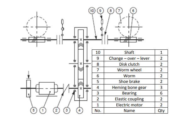
Assembly drawings show the entire device or system, as well as the placement and identification of each component. The roles of an assembly drawing include component identification, assembly order labeling, and occasionally even standard requirements. These drawings additionally include orthogonal plans, sections, elevations, weight, mass, a bill of materials (BOM), and other details. These drawings act as a common pictorial language for two technical people, allowing them to communicate.
Assembly drawings is For?
Assembly drawings are created for things, units, machines, and assemblies. They can also assist with mechanical drafting services, whether it’s putting together a simple kit, like furniture, or a sophisticated component of a mechanism. The following three specifications should be met by an assembly drawing:
- Maintenance requirement
- Operational requirement
- Manufacturing requirements
Assembly drawings’ significance
Any mechanism that is produced in bulk requires many precisely constructed assemblies and sub-assemblies. Without assembly drawings, technical information would need to be conveyed orally or in writing rather than graphically, which would lead to costly misunderstandings, errors, and lost time. Producing automobiles, aircraft, and other constructions that could potentially save lives has relied heavily on the efficient use of assembly drawings.
Assembly drawings typically provide the following information, which is sufficient to enable the assembly of a component:
- Several components or supporting assemblies.
- Enough orthogonal views that clearly demonstrate how the components work together.
- Section views display details and demonstrate how pieces go together.
- Only the overall size of the assembly or the machining processes required for assembly are indicated by dimensions on assembly drawings.
- Process requirements, protective coatings, and other pertinent information for assembling the item.
- A components list or bill of materials with a unique identifier for each item that will be used in the assembly.
- Information on the revision or issue

Types of assembly drawings
Assembly drawings are often categorized into the following five groups according to use:
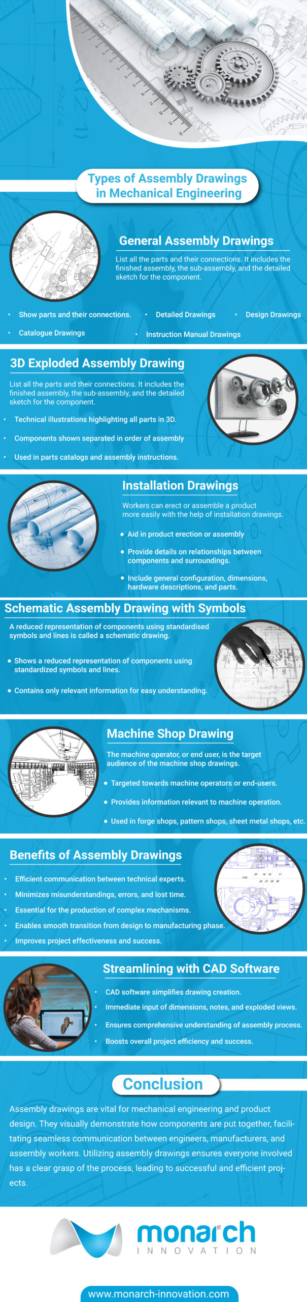
General Assembly Drawings
General assembly drawings list all the parts and their connections. It includes the finished assembly, the sub-assembly, and the detailed sketch for the component. Four categories can be used to classify the drawing:
- Design Drawings: Design drawings are created during the design phase and show various constructions, steel structures, and machinery that need to be put together from various angles. It helps in understanding how the object functions, including its shape and the clearances between different pieces.
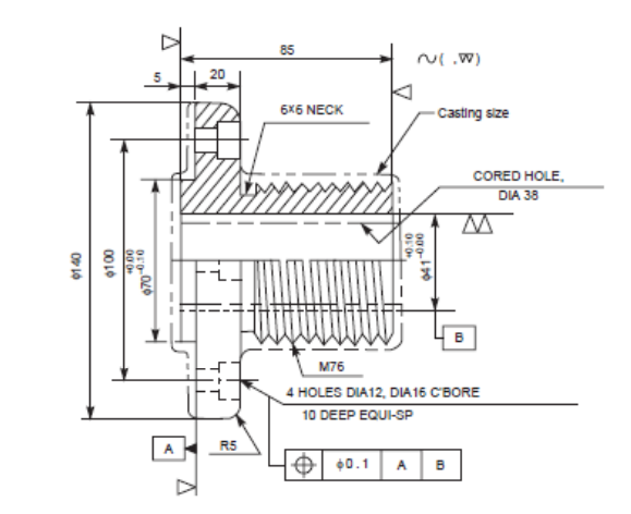
- Detailed Drawings: Detailed assembly drawings contain information about the materials, dimensions, joining techniques, etc., and show how the components fit together. It is possible to create magnified views of certain pieces and how they will fit together in addition to the standard assembly drawings. Sub-assemblies and individual parts are used to construct some types of machinery and buildings. Before being used in their final assembly, they can be put together and tested as a unit.
- Assembly Drawings for catalogues: Unique assembly drawings made specifically for company catalogues are known as assembly drawings for catalogues. These designs simply display the crucial information and measurements that a potential customer would find interesting.
- Assembly Drawings for instruction manuals: Every time a finished machine needs to be taken apart for shipping, reassembled, and installed at its location, assembly drawings for instruction manuals are required. To facilitate the reassembly process, each component in these drawings has a number.
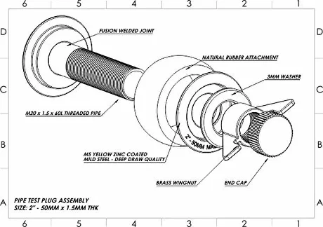
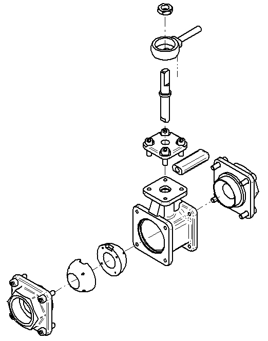
Exploded assembly drawing.
These are technical illustrations of an object that highlight all its parts. The 3D exploded diagrams produced by Assembly Modelling Services depict the components slightly separated or hanging in surrounding space in order of assembly. This provides a general sense of how the finished item will come together. These drawings are used in parts catalogues, assembly instructions, manuals, and other instructional materials because they are easy to grasp even for laypeople.
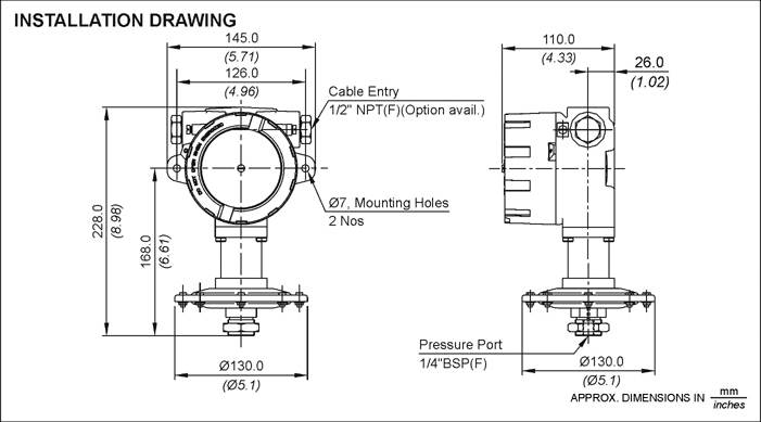
Installation drawings
Workers can erect or assemble a product more easily with the help of installation drawings. They provide details on the relationship between a component and its supporting or surrounding factors. Additionally, it will display a general configuration, dimensional data, hardware descriptions, and parts.
Schematic Assembly Drawing
A reduced representation of components using standardized symbols and lines is called a schematic drawing. Only relevant information is shown in schematic diagrams.
Machine Shop Drawing
The machine operator, or end user, is the target audience of the machine shop drawings. Since the dimensions and information relevant to the earlier steps are not important to the machinist, just the information pertaining to the machine’s operation is provided. Drawings from forge shops, pattern shops, sheet metal shops, etc. all operate on the same principle.
Conclusion
In conclusion, assembly drawings are vital for mechanical engineering and product design because they show how different parts and components are put together visually. Professionals may effectively explain the complexities of product assembly to engineers, manufacturers, and assembly workers by using a drawing sheet and assembly file, providing a smooth transfer from the design phase to the manufacturing phase. All parties engaged in the assembly process will have a clear grasp of the procedure with a well-prepared assembly drawing that includes dimensions and annotations added to the design sheet. The inclusion of dimensions, tolerances, and other pertinent data not only lowers the possibility of mistakes occurring during the assembly process but also improves the project’s overall effectiveness and success.
The process of producing new drawings from an existing assembly file is greatly streamlined by the usage of CAD software while developing assembly drawings. The software enables the immediate input of dimensions, notes, and exploded views to the drawing sheet, resulting in a thorough comprehension of the assembly procedure. By ensuring that everyone involved has a comprehensive grasp of the assembly process from the individual components to the finished system or product, these drawings eventually improve the project’s overall success and efficiency.
Ready to make your project a success with assembly drawing services? Contact us now!
FAQs
What is an assembly drawing?
An assembly drawing is a technical drawing that shows how different parts and components fit together to create a larger product or structure. It provides a visual representation of the assembly process and helps in understanding the relationships between the various parts. Assembly drawings are commonly used in engineering, manufacturing, and construction industries.
What are the different types of assembly drawings?
There are several types of assembly drawings, including exploded view drawings, detailed assembly drawings, and schematic assembly drawings. Each type serves a specific purpose and provides different levels of detail and information about the assembly.
What is the purpose of an assembly drawing?
The purpose of an assembly drawing is to show how different parts of a machine fit together and to help engineers and technicians understand how to assemble the machine.
What software is used to create assembly drawings?
Some popular software used for creating assembly drawings include AutoCAD, SolidWorks, CATIA, Siemens NX, and PTC Creo. These software programs offer a range of features and capabilities to create detailed and accurate assembly drawings.