MEP Drawings

Types of MEP Drawings

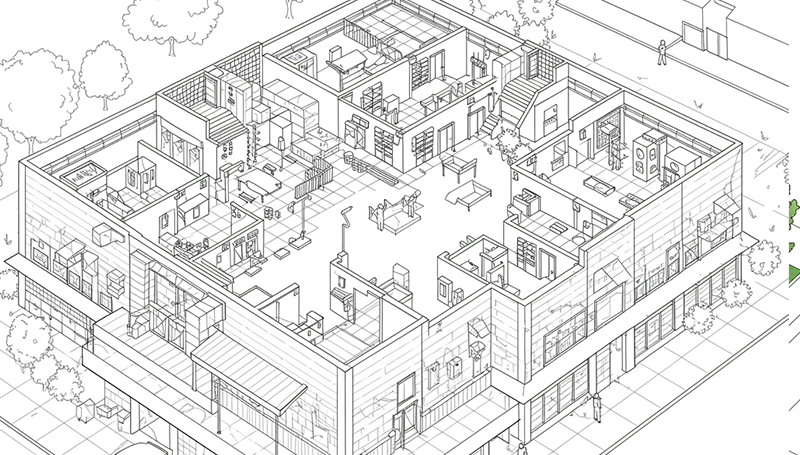
MEP drawings, in the construction industry, is a discipline of civil engineering that focuses on building safety, working, and energy-efficient structures. MEP refers to the mechanical, electrical, and plumbing systems which mainly serve as the backbone to the construction works. The Mechanical part of MEP concentrates on the heating, ventilation, and air-conditioning systems (HVAC system), the Electrical part of this discipline refers to the power supply and the Plumbing part focuses on the water supply and wastewater drainage. Revit MEP, AutoCAD, CADDUCT, Autodesk Inventor, and CAD PIPE are mainly used for preparing these drawings.

What is MEP Drawings?

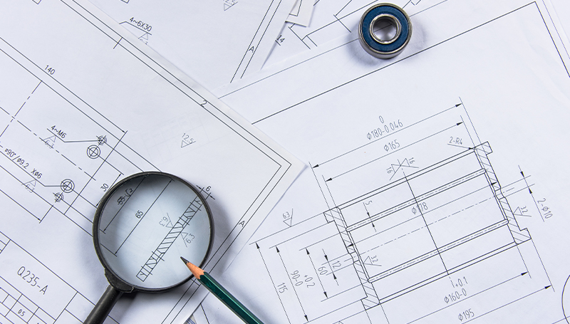
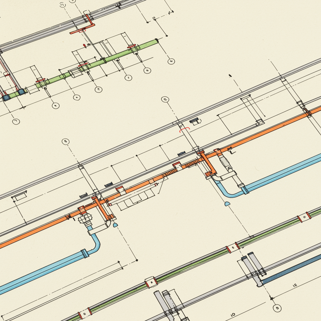
MEP drawing construction serves as a visual means of communicating how its components should be constructed and how they are going to function. They are widely used for sharing ideas across the construction industry. To make coordination drawings more convincing and to minimize perplexity, expert CAD drawing and drafting companies use familiar notation systems and units of measurement. Detailed MEP drawings help in the installation of the ductwork, plumbing, piping, electrical conduits, and fire protection piping such that the routing of each system does not interfere with the other. Every building’s MEP drawing set is unique, and generated after the installation of the building design documents.

Different Types Of MEP Drawings:-

Mechanical Drawings:

Mechanical Drawings are technical drawings that focus on the design, layout, and installation of mechanical systems in a building. These systems are primarily related to HVAC (Heating, Ventilation, and Air Conditioning), piping, and sometimes machinery used in industrial or commercial buildings. Mechanical drawings provide precise information on how these systems should be installed, maintained, and operated.

Key Components of Mechanical Drawings:

HVAC (Heating, Ventilation, and Air Conditioning) Layout: Shows the design and layout of HVAC systems, including ductwork, air handling units, diffusers, etc.

Ducting Layout: Specific drawing for duct routes, sizes, and airflow details.

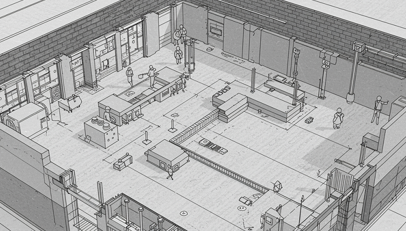
Equipment Layout: Indicates the location of major mechanical equipment such as chillers, boilers, and cooling towers.

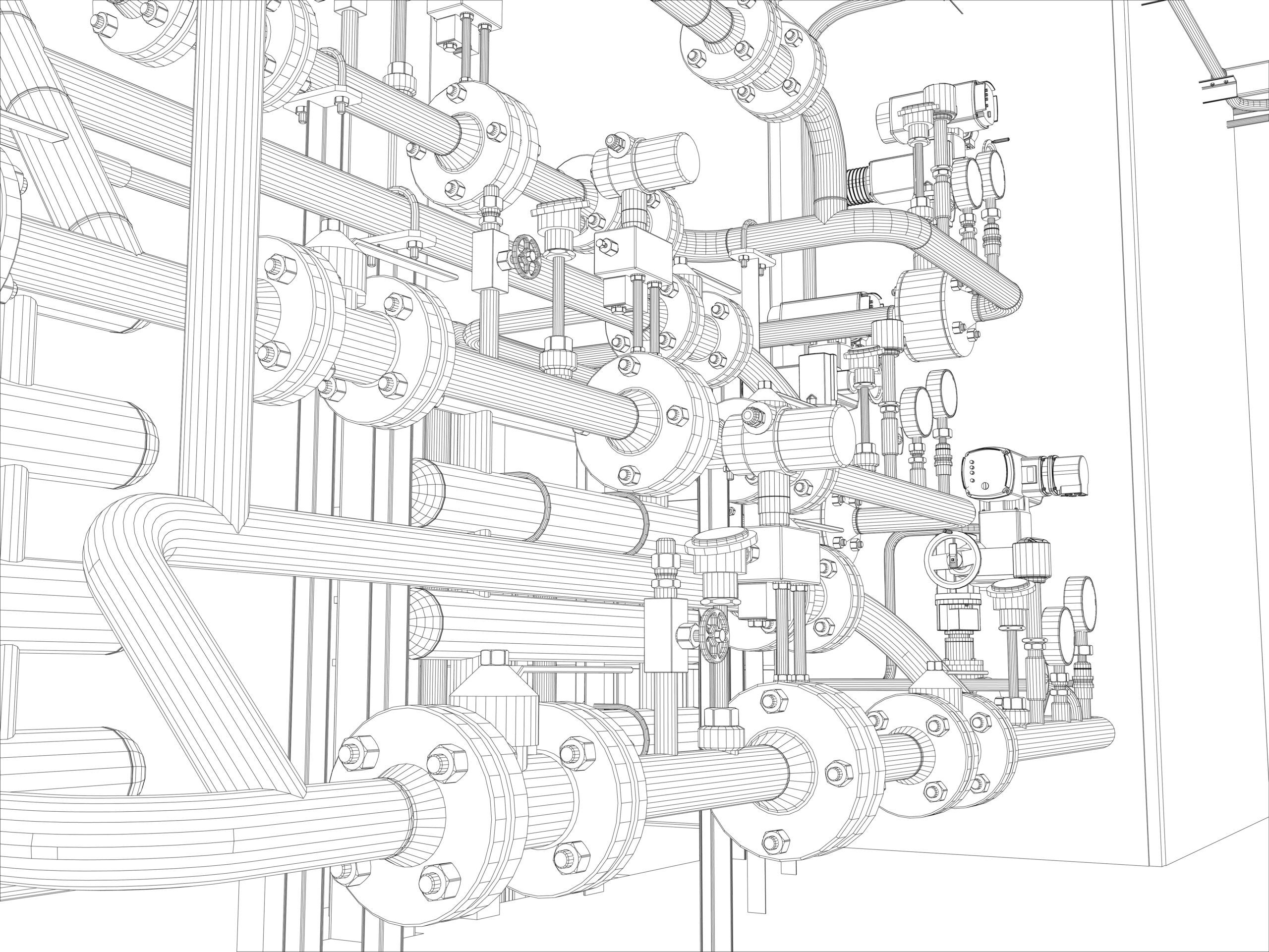
Piping Layout: Illustrates the piping routes for chilled water, hot water, steam, or other mechanical systems.

Electrical Drawings:

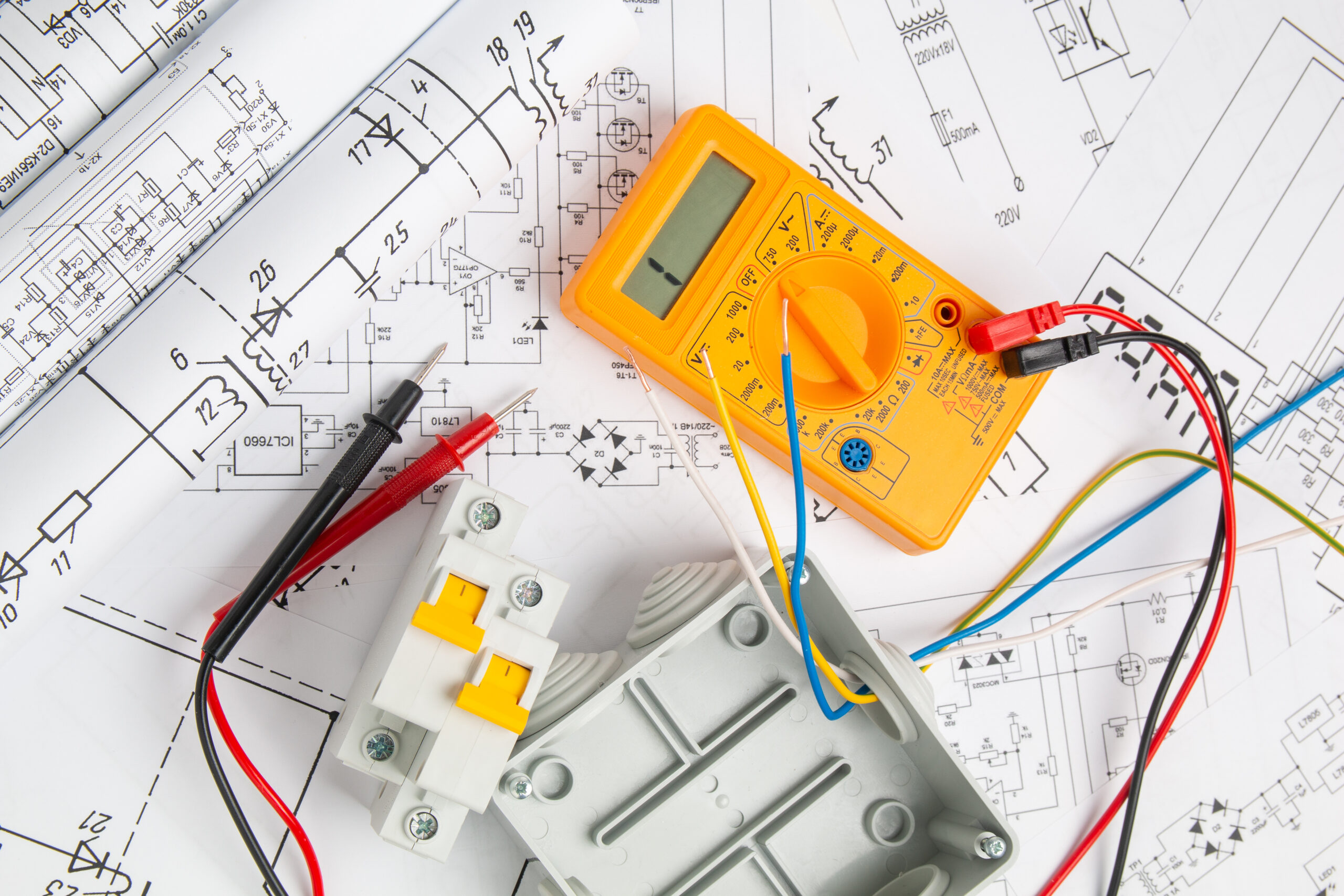
Electrical Drawings are detailed technical plans that represent the design, layout, and wiring of electrical systems within a building. These drawings are essential for the construction, installation, and maintenance of electrical infrastructure, ensuring that power is safely and efficiently distributed throughout a structure. Electrical drawings serve as a blueprint for electricians, engineers, and contractors, helping them to understand the electrical requirements and connections.

Key Components of Electrical Drawings:

Lighting Layout: Shows the positioning and specifications for lighting fixtures and controls.

Power Distribution Layout: Indicates the routing of electrical wiring and location of power outlets, panels, and switchboards.

Circuitry Diagram: Represents the wiring for electrical circuits, connections, and panel schedules.

Fire Alarm System Layout: Details the fire alarm devices, wiring, and control panels.

Low Voltage System Layout: Covers systems such as data, telephone, security, and AV systems.

Plumbing Drawings:

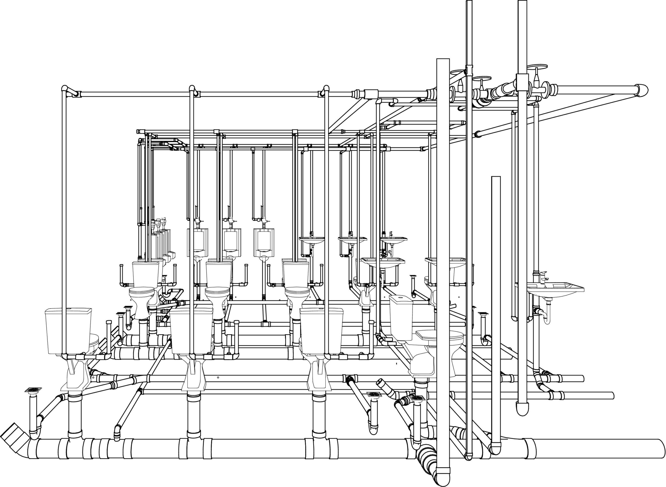
Plumbing Drawings are detailed technical plans that illustrate the layout, design, and installation of a building’s plumbing system. These drawings guide the construction and installation of piping, fixtures, drainage systems, and water supply, ensuring proper functioning and compliance with building codes. Plumbing drawings are critical for both residential and commercial projects, and they play a significant role in ensuring the safety, efficiency, and sustainability of water management within a building.

Key Components of Plumbing Drawings:

Water Supply Layout: Shows the layout of cold and hot water supply lines and fixtures like taps, sinks, and water tanks.
Drainage Layout: Provides details on the drainage system, including sewer lines, traps, and vents.
Sanitary System Layout: Focuses on the sanitary piping for toilets, wash basins, and other fixtures.
Gas Piping Layout: If applicable, shows the layout for gas pipes and appliances.

Fire Protection Drawings:

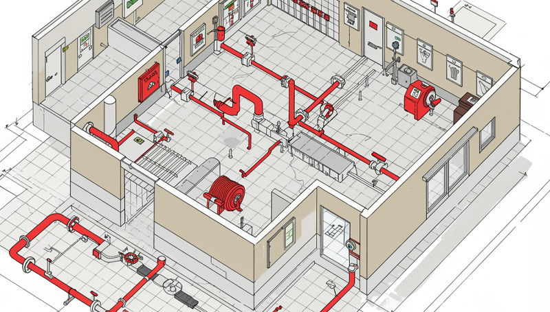
Fire Protection Drawings are specialized technical plans that detail the design and layout of fire protection systems within a building. These drawings are crucial for ensuring the safety of occupants and property by effectively detecting, suppressing, and controlling fires. Fire protection drawings help guide the installation, maintenance, and inspection of fire safety systems to meet regulatory standards and building codes.

Penetration Drawing

A Penetration Drawing is a specialized type of technical drawing used in construction, particularly in projects involving MEP (Mechanical, Electrical, and Plumbing) systems. It shows how various systems (pipes, ducts, conduits, or cables) pass through structural elements of a building, such as walls, floors, and ceilings. This ensures that the penetrations are correctly located and sealed for safety, functionality, and compliance with building codes.

MEP Shop Drawing Detailing

MEP Shop Drawing Detailing refers to the highly detailed and precise set of drawings used during the construction phase to represent the installation of mechanical, electrical, and plumbing systems. These shop drawings are different from design drawings as they provide a more granular view of the components and their installation, based on actual site conditions and contractor preferences.

Block-out and Sleeve Drawing

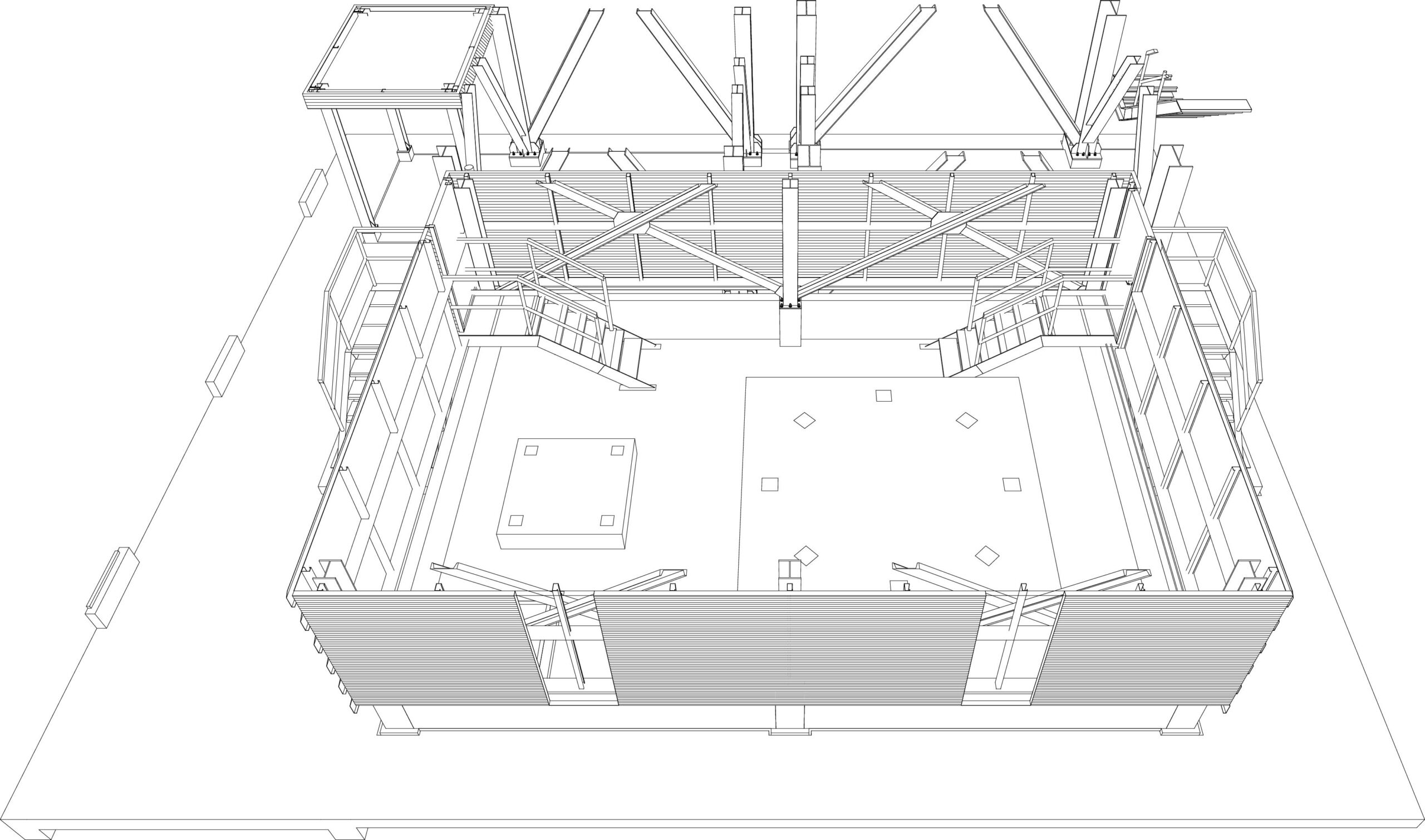
These drawings are useful for cement and steel contractors. The drawings are of great help when it is concerned with where to leave space on the floor and ceiling cutouts. Sleeve drawings are used to make sure that the holes left between the floors and the walls are properly placed for piping and ductwork.

Pipe Spool Drawing

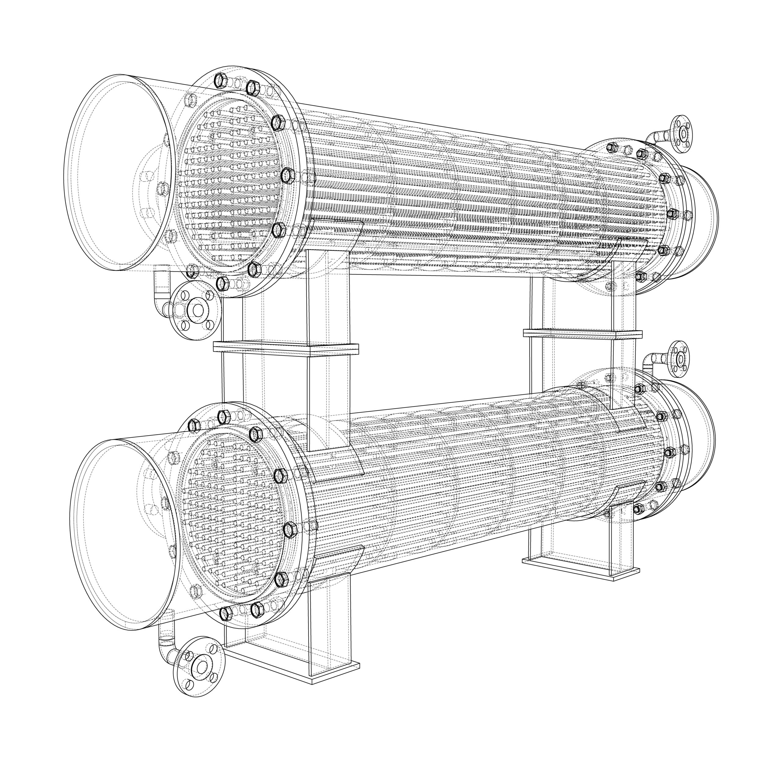
A spool is an assembly of pipes and is concerned with the components that can be pre-fabricated in the workshop for installation and shipped to the site afterwards for assembling. These drawings act as a guide to the plumbers to figure out what needs to be done. The spools are connected at different junctions throughout any concerned structure. The drawings are optimized to convey all the information that is essential for the fabricators to manufacture and assemble the spool accurately. A spool drawing is obtained after collecting the complete information of all parts welded together into a single drawing.

Coordination Drawing

Coordination is very important for the success of any building project. It simply means avoiding physical conflicts in the layout of the equipment and the routing of ducts, electrical piping, and drainage pipes through the building. When any building project has intense MEP requirements, the risk of interference problems is high. Elimination of coordination problems is a prerequisite for starting the construction work for projects with an intense MEP system. Coordination drawings are necessary to begin the construction work and eliminate any physical conflicts.

As-built Drawing

As-built drawings are final, detailed drawings that reflect the actual construction of a building or system after modifications and changes made during the construction process. Unlike original design or shop drawings, which represent the intended design, as-built drawings document the completed project as it exists, including any deviations from the original plans. These drawings are essential for future maintenance, repairs, and renovations.

Contact us for all your MEP BIM Services requirements, we at Monarch Innovation are happy to help.

FAQs

What is MEP in HVAC?

MEP in HVAC refers to the integration of the mechanical, electrical, and plumbing systems required for the proper functioning of HVAC systems in buildings.

What is MEP Specification?

MEP specifications refer to the detailed requirements and guidelines for the mechanical, electrical, and plumbing systems that are part of a construction project. These specifications outline the specific standards, materials, equipment, and installation procedures that are required for the MEP systems to meet the design intent and function properly.

What is the role of MEP in the construction industry?

MEP plays a crucial role in the construction industry as it is responsible for the design, installation, commissioning, and maintenance of the mechanical, electrical, and plumbing systems that are necessary for the safe and efficient operation of buildings.

MEP-BIM-Coordination

How MEP BIM Coordination Helps in the Construction Process

MEP drawings are a type of civil engineering that concentrates on the safety, functionality, and energy efficiency of structures in the construction business. Mechanical, electrical, and plumbing (MEP) systems are the backbone of building projects. MEP’s Mechanical section focuses on heating, ventilation, and air-conditioning (HVAC) systems, while the Electrical section deals with power supply and the Plumbing section with a water supply and wastewater outflow. These designs are mostly created with Revit MEP, AutoCAD, CADDUCT, Autodesk Inventor, and CAD PIPE.

MEP Coordination in the Construction Process

Before the primary building process begins, MEP Coordination is a strategy for detecting and resolving disputes across various professions such as architectural, plumbing, electrical, mechanical, and structural components. There should be coordination for each discipline, including the changes coming in, to bring these diverse designs into harmony. As a result, MEP BIM Coordination Services is a method for collaborating three primary design verticals, namely architecture, structural, and MEP designs of any infrastructure, and therefore becomes one of the review process’s requirements. Design, construction, and operation and maintenance domain expertise are all required for MEP coordination.

How does BIM help with MEP Coordination?

MEP Coordination functions by synchronizing all the construction work with the other disciplines that make up the structure, fabric, and exterior envelope of the structure. Within the prescribed, structural, and architectural limits, building services coordination allocates vertical and horizontal placements to specific system components. Following that, the coordination experts undertake coordination that focuses on extremely crowded regions to avoid building system interferences. This building service coordination, which takes place throughout the design creation and review process, represents the initial stage in building project coordination. These conflicts or interference must be detected early in the building process since mistakes and redundancy can cost a million dollars if not caught early enough.

Why is it Important to Manage your MEP Coordination Effectively?

We focus on providing clash-free BIM models along with co-ordinated MEP installation drawings, MEP-FS fabrication drawings, MEP-FS construction drawings, MEP-FS co-ordinations, MEP-FS shop drawings, as-built drawings, spool drawings, Architectural design documents, façade drawings, and more, thanks to the healthy expertise of our team in BIM Coordination offerings. We use 3D coordination services to provide an output model that includes Architectural, Structural, and MEP BIM models, as well as clash-free construction drawings sets.

The design inputs are initially coordinated through the BIM model, as a BIM coordination business. Before any difficulties are noticed on-site, any design conflicts or discrepancies in the inputs from various stakeholders are raised. After that, clash-free construction drawing sets are worked on, resulting in a quick time-bound execution. The BIM model is a one-of-a-kind tool for coordinating and detecting clashes between elements from many disciplines. We’ve worked on infrastructure projects and buildings at all levels of development (LOD).

What does an effective MEP coordinator look like?

The MEP sketch structure provides a visual representation of how the components should be built and how they will work. They’re commonly utilized in the building business for exchanging ideas. Expert CAD design and drafting businesses employ known notation methods and units of measurement to make coordinating drawings more believable and to reduce ambiguity. Detailed MEP designs aid in the construction of ducting, plumbing, piping, electrical conduits, and fire protection pipes so that each system’s route does not interfere with one another. The MEP drawing set for each building is unique, and it is created when the building design papers are installed.

The role of a project manager for managing MEP coordination efficiently!

  • Allows you to make the most of your building’s area.
  • Brings together the builder, contractor, architects, and engineers to address concerns early on and create a precise and correct design for the building project.
  • When we analyze the model with conflict detection software such as Navisworks and Revit, we can limit the number of change orders during on-site construction work, which can lead to human errors, saving money, time, and manpower for the building owner, contractor, and firm involved.
  • It allows numerous engineers to collaborate on a single model, which is then synchronized to reflect the changes made by each user in the project.
  • Based on the conflict detection reports, which include thorough mapping of the portions of the present structure, the engineers may make design alterations and enhancements to the existing structures, and this amended design can then be passed on to the contractor.

BIM-based design and construction (part of Virtual Design Construction) enable data-driven cooperation between architects, structural engineers, and MEP engineers from the start, increasing design confidence and simplifying phasing. As a result, the design-to-construction process has been drastically altered.

MEP Drawing

WHAT ARE THE ADVANTAGES OF MEP SHOP DRAWINGS?

Whether it is a construction project or designing the interiors and the exteriors of any building, the designers depend on the MEP (Mechanical, Electrical, and Plumbing) drawings for the smooth installation of the MEP components.

MEP shop drawings, considered as the backbone of the architectural and construction industry, are constituted by Mechanical, Electrical, and Plumbing drawings. These are the must-have drawings during the building phase of any project. A clear and concise MEP drawing serves as a clear path for the completion of the building which does not only save useful time but also the overall expenses. Without these drawings, it becomes impossible for the contractors to build a well-coordinated infrastructure and they may end up making mistakes and leading to huge losses in terms of time and money.

Constituents of MEP Drawings

Mechanical shop drawings

Mechanical shop drawings mainly deal with the heating, ventilation, and air conditioning (HVAC) systems and determine their placements. The HVAC represents the specifications for installation and fabrication of ducts, customized piping, and the other air-handling units. Besides these, the mechanical shop drawings also represent the transportation systems such as the lifts, escalators, infrastructural, and sometimes, industrial components.

Electrical shop drawings

The electrical systems in a building comprise a power supply and power distribution, access, control systems, security systems, information and communication system, interior and exterior lighting as well. Often there arises a conflict between the electrical and mechanical components inside a building. Therefore, with the help of comprehensive electrical shop drawings, contractors can accurately measure the layouts of electrical units to prevent any conflicts that may occur between the electrical and the mechanical components.

Plumbing shop drawings

The plumbing shop drawings represent the plumbing elements within a building which include piping and drainage system, garbage disposals, water carriers, etc. They specify fluid and air transport for heating and cooling, potable and non-potable water supply, and removal of waste.

Advantages of MEP Shop Drawings

  • If there is any potential flaw in the construction process, then with the help of MEP drawings, the contractor can directly refer to those drawing documents for locating the exact problem and fix it. In addition to that, if any parts or elements go missing or are found in damaged conditions, the contractor can easily find their substitutes after referring to those drawings. The licensing authorities also use the MEP shop drawings for effective planning, and also permitting and providing licenses for a fresh construction task.
  • With the help of MEP drawings, the accurate outline of the final assembly of products with the representation of their dimensions, cable or piping links, accessories, and weights are depicted and therefore the contractors can get an exact portrayal of how the construction design or supply process will look like during the on-site construction.
  • In the construction industry, it is necessary to keep a check on the cost factor, especially when it comes to MEP elements. The most important task regarding this is to estimate the cost of materials and installation, assembly cost, and elements cost, before the initiation of the construction project on-site in order to avoid overstocking and unnecessary wastages. 5D BIM helps in determining the cost of the components of the building, the types of materials to be used, and the assembling of the components and their installation. If there arises the case that the MEP building design is not accurate, orders can be placed with BIM Modeling which will prevent the wastage of time taken for manufacturing, reassembling, and re-installation.
  • MEP shop drawings help in the standardization of the building process and ensure that the products align with the industry standards, which enhances the chances of seeking licenses and building permits. If anyone is unsure about the standards to be followed, they can ask the BIM engineers for designing MEP drawings, conforming to the AEC industry standards and regulations.
  • The modern BIM technology gives a lot of freedom to its users which enables smooth collaboration among the project stakeholders. Cloud access improves the on-site collaboration and communication thereby, helping the sharing of the MEP shop sets with all AEC project stakeholders within the organization. This shared-cloud setup facilitates practical training for students and other such interested people who want to join the AEC industry.
  • An accurate BIM shop drawing besides being a reason for a long sustainable infrastructure enhances the brand value. If an organization adds its logo to its documents, it adds value to its brand. Therefore, there is no doubt in saying that a well-designed drawing leads to great infrastructure and a great infrastructure leads to a well-established brand.

If there is any requirement of shop drawings for MEP within your building, Monarch Innovation should be your first choice for getting your work done with utmost perfection. Monarch Innovation is a credible and reliable Design & Engineering company providing shop drawings services. They have a unit of skilled and experienced design engineers and architects who design every component of the building with much precision. Contact Monarch Innovation for having your MEP drawings designed by them.

Previous Next
Close
Test Caption
Test Description goes like this
Add to cart
Open chat
Hello,
Welcome to Monarch Innovation!

How Can I Help You..?