MEP drawings in construction focus on mechanical, electrical, and plumbing systems, ensuring building safety, functionality, and energy efficiency. It refers to the mechanical, electrical, and plumbing systems which mainly serve as the backbone of the construction works. MEP consists of Mechanical (HVAC systems), Electrical (power supply), and Plumbing (water supply and drainage). Revit MEP, AutoCAD, CADDUCT, Autodesk Inventor, and CAD PIPE are mainly used for preparing these drawings.
What is MEP Drawings?
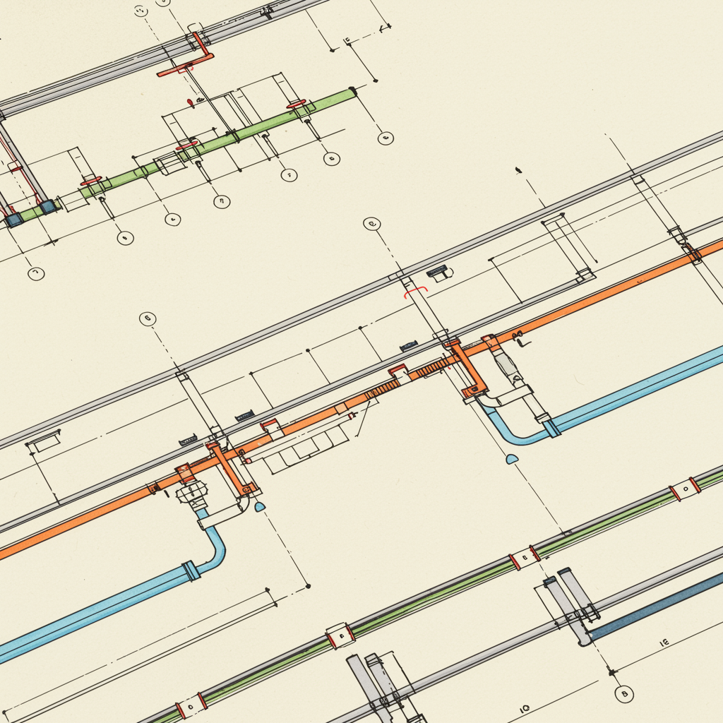
MEP drawing construction visually communicates the construction and functionality of components, ensuring clarity and coordination across the construction industry. Expert CAD drafting companies use standard notation systems and measurement units to enhance clarity in coordination drawings. Detailed MEP drawings ensure proper installation of ductwork, plumbing, piping, electrical conduits, and fire protection systems without conflicts. Every building’s MEP drawing set is unique and generated after the installation of the building design documents.
Different Types Of MEP Drawings:-
1. Mechanical Drawings:
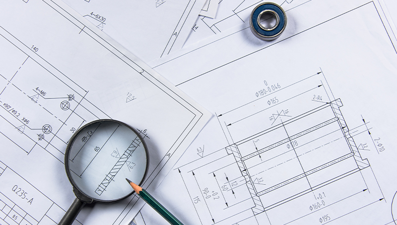
Mechanical Drawings are technical drawings that focus on the design, layout, and installation of mechanical systems in a building. These systems are primarily related to HVAC (Heating, Ventilation, and Air Conditioning), piping, and sometimes machinery used in industrial or commercial buildings. Mechanical drawings provide precise information on how these systems should be installed, maintained, and operated.
Key Components of Mechanical Drawings:
- HVAC (Heating, Ventilation, and Air Conditioning) Layout: Shows the design and layout of HVAC systems, including ductwork, air handling units, diffusers, etc.
- Ducting Layout: Specific drawing for duct routes, sizes, and airflow details.
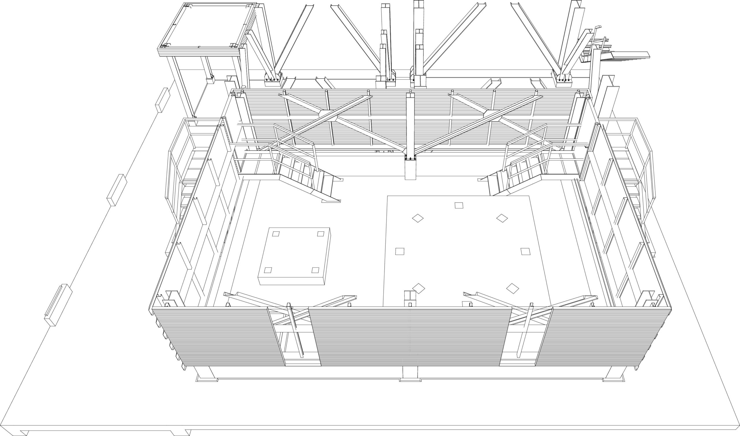
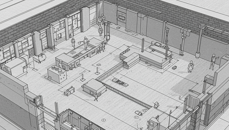
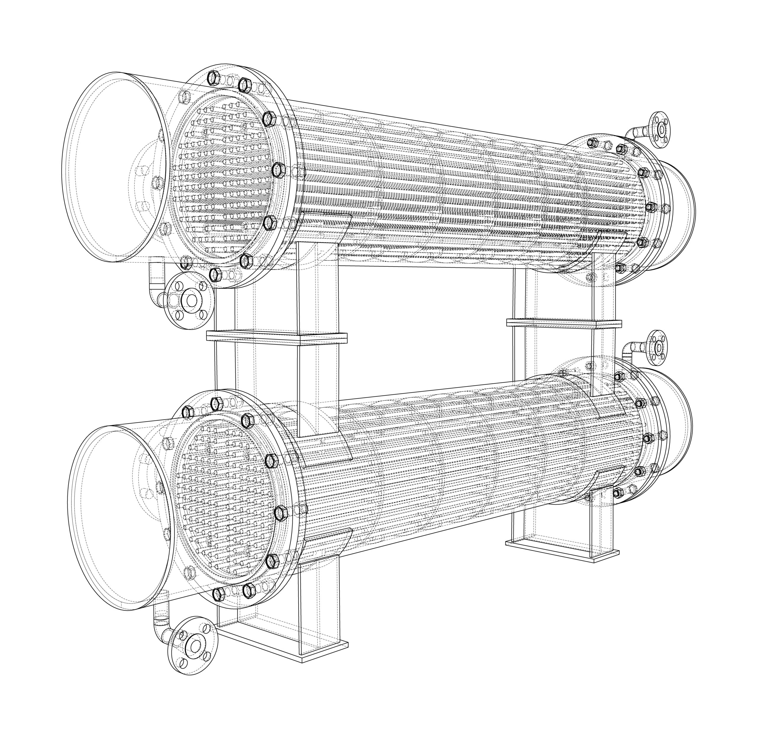
- Equipment Layout: Indicates the location of major mechanical equipment such as chillers, boilers, and cooling towers.
- Piping Layout: Illustrates the piping routes for chilled water, hot water, steam, or other mechanical systems.
2. Electrical Drawings:
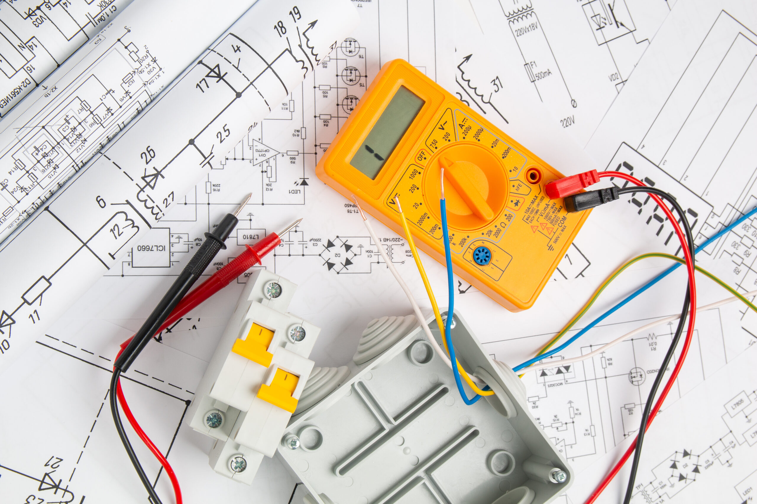
Electrical Drawings are detailed technical plans that represent the design, layout, and wiring of electrical systems within a building. These drawings are essential for the construction, installation, and maintenance of electrical infrastructure, ensuring that power is safely and efficiently distributed throughout a structure. Electrical drawings serve as a blueprint for electricians, engineers, and contractors, helping them to understand the electrical requirements and connections.
Key Components of Electrical Drawings:
- Lighting Layout: Shows the positioning and specifications for lighting fixtures and controls.
- Power Distribution Layout: Indicates the routing of electrical wiring and location of power outlets, panels, and switchboards.
- Circuitry Diagram: Represents the wiring for electrical circuits, connections, and panel schedules.
- Fire Alarm System Layout: Details the fire alarm devices, wiring, and control panels.
- Low Voltage System Layout: Covers systems such as data, telephone, security, and AV systems.
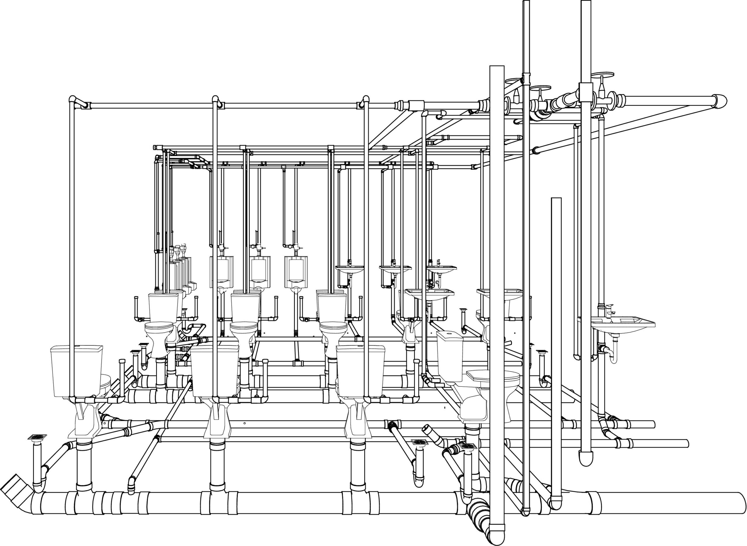
3. Plumbing Drawings:
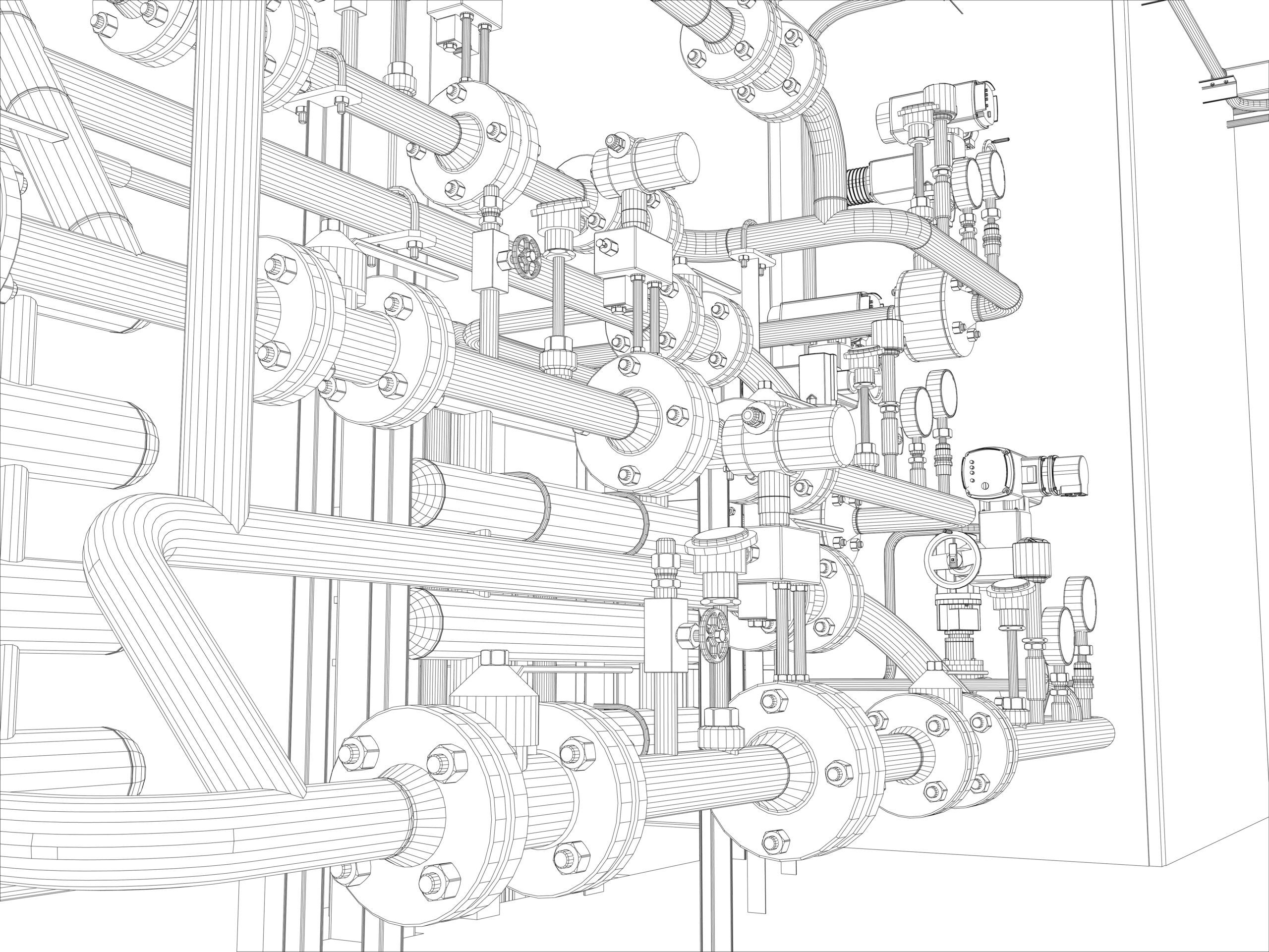
Plumbing Drawings are detailed technical plans that illustrate the layout, design, and installation of a building’s plumbing system. These drawings guide the construction and installation of piping, fixtures, drainage systems, and water supply, ensuring proper functioning and compliance with building codes. Plumbing drawings are critical for both residential and commercial projects, and they play a significant role in ensuring the safety, efficiency, and sustainability of water management within a building.
Key Components of Plumbing Drawings:
- Water Supply Layout: Shows the layout of cold and hot water supply lines and fixtures like taps, sinks, and water tanks.
- Drainage Layout: Provides details on the drainage system, including sewer lines, traps, and vents.
- Sanitary System Layout: Focuses on the sanitary piping for toilets, wash basins, and other fixtures.
- Gas Piping Layout: If applicable, shows the layout for gas pipes and appliances.
4. Fire Protection Drawings:
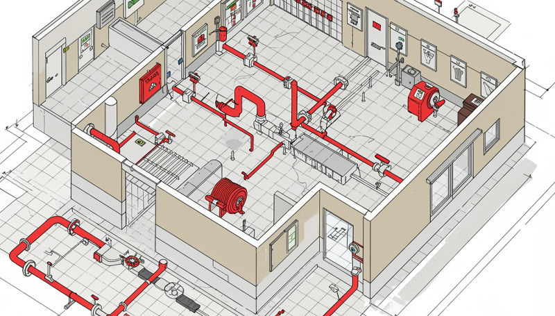
Fire Protection Drawings are specialized technical plans that detail the design and layout of fire protection systems within a building. These drawings are crucial for ensuring the safety of occupants and property by effectively detecting, suppressing, and controlling fires. Fire protection drawings help guide the installation, maintenance, and inspection of fire safety systems to meet regulatory standards and building codes.
5. Penetration Drawing
A Penetration Drawing is a specialized type of technical drawing used in construction, particularly in projects involving MEP (Mechanical, Electrical, and Plumbing) systems. It shows how various systems (pipes, ducts, conduits, or cables) pass through structural elements of a building, such as walls, floors, and ceilings. This ensures that the penetrations are correctly located and sealed for safety, functionality, and compliance with building codes.
6. MEP Shop Drawing Detailing
MEP Shop Drawing Detailing refers to the highly detailed and precise set of drawings used during the construction phase to represent the installation of mechanical, electrical, and plumbing systems. These shop drawings are different from design drawings as they provide a more granular view of the components and their installation, based on actual site conditions and contractor preferences.
7. Block-out and Sleeve Drawing
These drawings are useful for cement and steel contractors. The drawings are of great help when it comes to determining where to leave space on the floor and ceiling cutouts. Sleeve drawings ensure proper placement of holes between floors and walls for piping and ductwork.
8. Pipe Spool Drawing
A spool is an assembly of pipes that includes components pre-fabricated in the workshop for installation and later shipped to the site for assembly. These drawings guide plumbers in understanding the required tasks. Spools connect at various junctions throughout the structure. The drawings provide essential information to help fabricators manufacture and assemble the spool accurately. A spool drawing compiles detailed information about all welded parts into a single, comprehensive illustration.
9. Coordination Drawing
Coordination is very important for the success of any building project. It simply means avoiding physical conflicts in the layout of the equipment and the routing of ducts, electrical piping, and drainage pipes through the building. When any building project has intense MEP requirements, the risk of interference problems is high. Elimination of coordination problems is a prerequisite for starting the construction work for projects with an intense MEP system. Coordination drawings are necessary to begin the construction work and eliminate any physical conflicts.
10. As-built Drawing
As-built drawings document the final construction, reflecting changes made during the process, unlike design or shop drawings.
Unlike original design or shop drawings, which represent the intended design, as-built drawings document the completed project as it exists, including any deviations from the original plans. These drawings are essential for future maintenance, repairs, and renovations.
Conclusion
MEP drawings are essential for ensuring accuracy, efficiency, and seamless coordination in construction projects. From HVAC systems to plumbing and electrical planning, precise MEP drafting minimizes conflicts and optimizes building performance. At Monarch Innovation, our expert team is committed to delivering high-quality MEP BIM services that enhance project execution and long-term sustainability.
Contact us for all your MEP BIM Services requirements, we at Monarch Innovation are happy to help.
FAQs
1. What is MEP in HVAC?
MEP in HVAC refers to the integration of the mechanical, electrical, and plumbing systems required for the proper functioning of HVAC systems in buildings.
2. What is MEP Specification?
MEP specifications refer to the detailed requirements and guidelines for the mechanical, electrical, and plumbing systems that are part of a construction project. These specifications define the standards, materials, equipment, and installation procedures needed to ensure MEP systems meet the design intent and function properly.
3. What is the role of MEP in the construction industry?
MEP plays a crucial role in the construction industry as it is responsible for the design, installation, commissioning, and maintenance of the mechanical, electrical, and plumbing systems that are necessary for the safe and efficient operation of buildings.