Types of Construction Drawings

46 Major Types of Construction Drawings Used in Building Construction

Construction drawings are used for a wide variety of reasons and applications in construction and architectural projects and activities.

What is a construction drawing?

It is a graphical representation of what will be built, how it will be laid out, the components, framework, and dimensions. There is a construction drawing highlighting the details of every aspect of a construction project.

Construction Drawings including each of its subtypes are helpful to different groups of workforce assigned with doing or overlooking the various tasks that make up a construction project.

How are construction drawings made?

Rarely are construction plans drawn by hand anymore. They are either sketched and rendered using computer-aided drafting such as computer-aided design (CAD) software. And in recent times, Building Information Modeling (BIM) software has made it easy to render and visualize in detail the virtual construction models (VCM).

To know more about BIM services, budgeting, and how they can benefit your project, reach out to us at Monarch Innovation for all queries, assistance, and collaborations.

Top 46 most common types of Construction drawings use regularly in construction industries.

Architectural Drawings
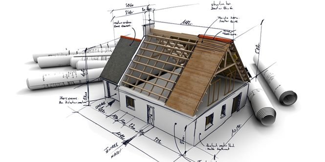
Architectural Drawings are drawing work that is used in building drawings to depict the dimensions, depth, and layout of the actual building, prior to beginning the construction. Architectural Drawings act as a blueprint construction, drawn to scale, to help the engineers visualize the project.

Various types of Architectural Drawings commonly used are:

1. Block Plan

This drawing gives a layout of the site or the buildings in the surrounding area, laid out on a map drawn to scale.

  • It gives a firsthand idea of the roads, boundaries and other such details that are necessary to understand where your construction site lies.
  • It helps the person dealing with your construction plan or project request to understand what and where you are proposing it and help you out with it too.
  • Block plans are made in relation to Ordnance Survey Maps and the recommended scales used are 1:2500, 1:1250 or 1:500.

    Block Plan Construction Drawing

2. Foundation plan 

Not to be mistaken for just the ground or basement floor plan. Foundation Plans are drawing work to render any of the floors of the building being constructed. They help visualize the dimension, size, shape, height and configuration of rooms/stairs/landings with each other.

Foundation Plan Construction Drawing
Foundation Plan

3. Floor plans

In-depth rendering of the layout of the rooms for each floor. It describes in 2D the orientation of rooms and components to each other. Floor plans may or may not be utilized in commercial or non-commercial building projects, but it is necessarily still made as part of the drawing work.


floor plan designed building drawing
Floor plan designed building drawing

4. Sectional Drawings

These are drawings that depict a part or whole of the framework in sliced form. It helps understand the measurements of various building components with each other, the materials used in the construction of those components, the height, depth, and hollowness, etc.

Sectional Drawing
Sectional Drawing

5. Elevation Drawings 

These architectural drawings offer an aesthetic overview of the various components of the building such as columns, windows, and doorframes. It also helps understand the relative surface, internal markings, and relative height of these different components to each other.

Typical elevations drawing
Elevations Drawing https://www.designingbuildings.co.uk/

6. Site Plan 

A site plan is a detailed drawing that shows the entire construction site with property boundaries, existing structures, proposed new building locations, site grading/topography, and other site features like landscaping, parking areas, utilities, etc.

Typical Site Plan
Typical Site Plan https://www.designingbuildings.co.uk/

7. Isometric Drawing

An isometric drawing is a type of 3D parallel projection used to represent objects pictorially. It shows three sides of an object with the vertical lines projecting at a 30-degree angle and the horizontal lines projecting at a 30-degree angle.

8. Axonometric Drawings

Axonometric drawings are types of 3D parallel projections that show an object in an oblique/angled view. They include isometric, dimetric, and trimetric drawings depending on the exact angle used for the horizontal and vertical lines.

9. Presentation Drawings

Presentation drawings are highly detailed renderings or 3D models used to communicate and visualize the design intent for clients, stakeholders, and approving authorities. They showcase the appearance, materials, and aesthetic qualities of the project.

10. Survey Drawings

Survey drawings represent the existing conditions on a construction site based on detailed field survey data. They show site topography, boundaries, existing structures, underground utilities, and other existing features crucial for planning new construction.
11. Location Drawings

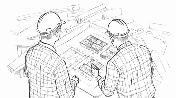
Location drawings are used to indicate the specific position or location of building components, systems like HVAC ducts, plumbing pipes, electrical conduits, etc. within the overall construction. They help avoid conflicts during installation.

12. Assembly Drawings 

Assembly drawings illustrate in detail how different components and materials fit together during construction. They provide crucial information on the sequence, connections, and relationships between various building parts to guide proper assembly.

Assembly drawing
Assembly Drawing https://www.designingbuildings.co.uk/

13. Parametric Drawing

A parametric drawing is created using parametric modeling software that allows the drawing views to automatically update when design parameters like dimensions or specifications are changed. This ensures consistent, coordinated drawings across all sheets.

14. Design Drawing

Design drawings are conceptual drawings that architects create early in the design process to explore, develop, and communicate design ideas and concepts to clients before moving to more detailed stages. They convey the building’s overall form, massing, and character.

15. Reflected Ceiling Plan

A reflected ceiling plan is a drawing that shows the layout of the ceiling as if it’s viewed from above by someone standing in the room looking upwards. It depicts ceiling-mounted elements like light fixtures, diffusers, speakers, etc.

16. Record / As-built Drawings

Record drawings, also called as-built drawings, are the final set of drawings updated to incorporate all the construction changes, modifications, and as-built conditions from the actual construction process. They document the constructed project accurately.

House floor plan featuring kitchen and living room. As-built Drawings
As-built Drawings https://www.designingbuildings.co.uk/

Structural Drawings

Structural Drawings also serve as civil engineering drawings. They are useful in understanding the physical nitty-gritty of a building framework. They act as a structural design guide for the workers and on-site engineers. Common types of structural drawings are:

17. General Note

An overview of all the codes, procedures, and abbreviations, etc required to give a comprehensive guide to getting to work on the construction site. This includes concrete mix, details for other structural drawings, lengths and construction types of each component, etc.

18. Excavation Drawing

This civil engineering drawing describes the dimensions and positions for the excavation process prior to the actual building work. It covers details like tunneling, shafts, removal of soil, grid plans, etc. required to start the groundwork.

19. Column Layouts

These structural drawings include the layouts of the way columns will be laid out. It makes it easier for contractors to plan the layout of the building and start the process by identifying the position and distance between columns across the floor.

20. Beam Layouts

It includes all the beam-like structures, such as the ones supporting the roof and the windows, or the beams used for strengthening purposes. They are designed for each floor and cover the length, height, material, etc.

21. Roof slab layouts

this civil engineering drawing describes the exact dimensions of all the slabs required for roofs or slants. It can be designed over AutoCAD software as it requires precision and data.

22. Section Plan

A section plan is a drawing that shows a cross-sectional vertical or horizontal view through the building by cutting through it. Section plans clarify the internal construction, framing and relationships between different structural elements.

23. Detail Drawings

Detail drawings are large-scale drawings focused on specific construction details and connections between different structural components. They provide in-depth, magnified information crucial for installation and assembly by showing reinforcements, fasteners, dimensions, etc.

25. Component Drawing

Component drawings focus on providing comprehensive details and dimensions of individual structural elements like beams, columns, footings, etc. They serve as a reference for manufacturing, fabrication, or on-site construction of these components.

Typical Component Drawing
Component Drawing https://www.designingbuildings.co.uk/

26. Column Layout

A column layout plan indicates the locations of all structural columns in the building along with the column gridlines and dimensions. It helps ensure proper positioning and installation of columns during construction.

27. Plinth Beam Layout

The plinth beam layout plan shows the layout, positions and dimensions of all plinth beams or grade beams that will be constructed below and support the load-bearing walls at the foundation level.

28. Lintel Beam Layout

A lintel beam layout plan depicts the locations, sizes and geometry of all lintel beams provided over wall openings like doors, windows, etc. to transfer loads across those openings safely.

29. Roof Beam Layout / Shuttering

The roof beam layout plan shows the framing layout for supporting the roof structure with dimensions for beam sizes and spacing. The shuttering layout indicates formwork patterns/positioning for concrete roofs.
30. Framing Plan

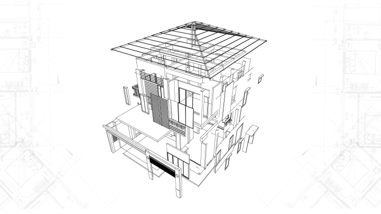
A framing plan is a structural drawing that illustrates all the load bearing, framed elements in the building like floors, walls, and roofs. It clarifies the overall framing system, member sizes, connections, and relationships.

31. Engineering Drawing

An engineering drawing is a technical drawing produced by structural engineers with precise dimensions, calculations and specifications related to the building’s structural design, analysis and detailing following relevant engineering codes.

Engineering Drawing
Engineering Drawing

32. Installation Drawings

Installation drawings provide clear instructions and details guiding the installation processes for prefabricated structural components or building systems manufactured off-site for easy assembly on the construction site as per design specifications.

Typical Installation Drawing
Installation Drawing https://www.designingbuildings.co.uk/

MEP Drawings

33. Electrical drawings

Most residential construction drawings or commercial construction drawings require a functional outline of the number of power outlets, light fixtures, fan fixtures, etc. They also include the wiring pattern and details about the electrical load it can carry. Common details included in Electrical Drawings are:

  • Earthing layout
  • Light fixture layout
  • Generator and other equipment
  • Cable tray layout
  • Hazardous area classifications
  • Lighting protection system

    Electrical drawings
    Electrical drawings https://www.designingbuildings.co.uk/

    34. Plumbing Drawings

Just like electrical layouts, plumbing is another part of any residential or commercial construction drawing that marks the points where plumbing components need to be set up. Space is left here accordingly for further pipe and sanitary ware fixtures to be added once the structural component is finished. Plumbing drawings commonly include:

  • Pipes – water pipes, drainage pipes, internal pipes
  • Material of pipes
  • Outlet points – taps, sinks, tanks etc
  • Position and location of pipes and outlets

    35. HVAC/Mechanical Drawings

These are known as mechanical construction drawings. They provide details and a design framework for heating and ventilation systems in a building. Central heating/cooling, air conditioning vents, ventilators, etc are all included according to the need and site of the building plans. Builders use these design constructs in their process accordingly.

Hospital Building HVAC Duct Design Layout Plan
HVAC Drawing https://thumb.cadbull.com/

36. Piping Spool Drawings

Piping spool drawings are detailed drawings focused on specific prefabricated sections of pipes called spools used in industrial piping systems. They show precise dimensions, connections, and routing of these spool sections.

37. Firefighting Drawings

In today’s construction systems, safety design is paramount. Firefight Drawings are also a part of blueprint drawings of a building that allocate points for fire hoses, fire escapes, water outlets, sandbags, or any other fire safety equipment required by the regulatory body overseeing the project.

Additional Drawing Types

38. Production Drawings

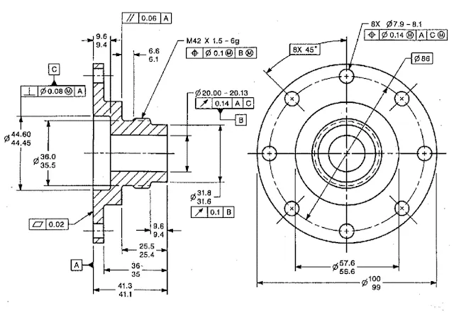
These Construction Drawings are used to convey functional information to the workers and engineers on site. It describes the materials, the assembly of various parts, the tools required, the dimensions, and other information required during the process. It may also include additional information or an infographic on how to meet those set requirements.
Production Drawings
Production Drawings https://miro.medium.com/


39. Environmental Plans

Making sure environmental guidelines and management is properly followed is a part of construction projects that cannot be overlooked. The aim is to minimize environmental damage and future negative impacts of the construction project. It includes measures like:

  • Chemical disposal mechanisms
  • Management of erosion and sedimentation
  • Outlining environmental guideline compliance measures
  • Measures to handle accidents and emergencies like fire

    40. Finishing Drawings

These include finer and more detailed plans of the building after the whole structural and architectural framework has been set up. These are required for the aesthetic and functional value of the building. These construction drawings include details of:

  • Tile patterns,
  • Floor patterns
  • False ceilings
  • Paint colors and textures
  • Plaster
  • Woodwork
  • Motifs and designs

41. Location Plan

A location plan is a simple drawing that shows the location of the construction project site about its surroundings like nearby roads, landmarks, neighborhoods etc. to help identify and access the site easily.

42. Shop Drawings / Fabrication Drawings

Shop drawings or fabrication drawings provide precise dimensions, details, and instructions from the manufacturers/suppliers for prefabricated construction components, materials, or equipment off-site before delivery to the construction site for installation.

Shop Drawings
Shop Drawings https://www.designingbuildings.co.uk/

43. Scale Drawings

Scale drawings refer to any plans, sections, elevations, or detail drawings that are produced using precise measurement scales to represent actual dimensions accurately, allowing dimensions to be determined from the drawings reliably.

Scale Drawings
Scale Drawings https://www.designingbuildings.co.uk/

44. Perspective Drawings

Perspective drawings are three-dimensional views or illustrations drawn to show depth and provide a view of the subject from a particular vantage point as it would appear to the human eye.

45. Working Drawings

Working drawings comprise the complete set of finalised technical drawings including plans, sections, elevations, and details issued to construction crews on site with all required information for executing the building construction work as per the design.

Working Drawings
Working Drawing https://www.designingbuildings.co.uk/

46. Technical Drawings

Technical drawings are a general term encompassing all types of precise drawings used to convey technical or engineering information about an object, product, system or structure through illustrations, dimensions, notes, symbols, and conventions.

Technical Drawings
Technical Drawings

To get professional advice and assistance on your construction projects, contact us at Monarch Innovation for our host of BIM, Building Design, and Mechanical Engineering services.

Backed up by experience in this field, we would be happy to help you get insights, in-depth analysis, and coordinate your project plans to make the process hassle-free.

FAQs


What are construction drawings?

Construction Drawings are a graphical representation of what will be built, how it will be laid out, the components, framework and dimensions. There is a construction drawing highlighting the details for every aspect of a construction project.

What are the different types of construction drawings?

Below are the set of basic drawings included in Construction drawings:
1. Elevation drawings – These drawings offer an overview of the individual components that make up the structure, plus the structure as a whole.
2. Sections – Sections are slices of the building, to showcase the inner dimensions.
3. Floor Plans – The rendering of each of the floors in a building, which lays out the rooms, the doors, the positioning of the stairs, windows, columns, kitchen, slabs, etc all in 1D. It helps one to understand the orientation of the rooms and other physical structures that make up the floor.
4. Details – As the name suggests, these are drawings that focus more on individual components of a building, in detail.

What are architectural construction drawings?


Architectural Construction Drawings are drawing work that is used in building drawings to depict the dimensions, depth and layout of the actual building, prior to beginning the construction. Architectural Drawings act as a blueprint construction, drawn to scale, to help the engineers visualize the project.

How to make construction drawings?


Construction drawings usually include a set of working drawings that cover different aspects of the project plan. These drawings usually comprise Elevation drawings, Floor Plans, Sections and Detail Drawings.

point cloud scan to bim

Benefits of Point Cloud Scan to BIM

One of the recent advancements in the AEC industry to increase its productivity is the Scan to BIM technology. The extensive use of the Scan to BIM process can be seen in renovation projects. With the help of laser scanning technology, data are derived which are used to develop productive 3D BIM models.

The companies who work on As-built projects, renovation, and refurbishment of old buildings depend on point cloud services. Rather than using the manual surveys using the measuring tapes, this technology implements the laser scanning process for mapping the buildings. These point cloud images (also referred to as scanned images) are registered and are converted into 3D Revit models or 2D CAD drawings. This process is termed as “Scan to BIM Modeling” or “Point Cloud to BIM Modeling“.

The Scan to BIM services finds its use in restoring heritage buildings, government buildings, old commercial or residential setups, and so on. These scans penetrate deeper with points and beams to detect walls, ducts, beams, or pipe batches in the geometry or outer paradigm of the building. On the basis of these scans, the point cloud BIM model is made to determine the look of the site post-construction, to extract the information and to plan the project phase, and so on. With the use of Point cloud BIM model technologies, the time consumption and cost are reduced to a greater extent.

Workflow of Scan to BIM Process

  • At first, Revit should be opened for including point cloud data in the Revit project.
  • Once Revit becomes accessible, the next step in the procedure is to convert the available scanned data into effective file formats.
  • Generally, convert raw scanned data is converted into point cloud files using Autodesk® ReCap.
  • During the indexing process, the raw scanned data should be transformed into appropriate cloud files.
  • After indexing, the raw scanned data is transformed into file formats like .rcp (Reality Capture Project File) format and .rcs (Reality Capture Scan files) format.
  • Soon after getting the .rcp and .rcs file formats, users can link the point cloud files within a Revit project.
  • Numerous .rcs files are included in an .rcp file.
  • The next task is to click on the ‘Insert tab’ first and then ‘Link Panel’. After that, the ‘Point cloud’ icon within the Link panel should be clicked on.
  • After selecting Point cloud, the files which should be linked to the project should be identified.
  • Depending on the requirement, either the .rcp extension file or the .rcs extension file can be selected.
  • In order to insert the file into the Revit Project, a Point Cloud tool should be used.
  • Once a suitable file is selected, then the next thing that should be focused on is how to position a file in the project.
  • A file can be positioned in the project either by selecting Auto-center to center option or by using an option among Auto – Origin to Origin, Auto – Origin to Last Placed, and Auto –By Shared Coordinates.
  • Once an effective file positioning option is chosen, then the point cloud file can be linked to the project by clicking on “open’.

Benefits of Point Cloud Scan to BIM

The benefits of point cloud laser scan to BIM in construction life cycle stages are :

  1. Design building phase In this phase of construction, the designers comprehend the site conditions in a suitable way with the help of an as-built model of the construction site and the surrounding buildings, enabling improved construction design decisions.
  2. Construction stage – During construction, the point cloud laser scan to BIM can be helpful in locating any discrepancies between the as-built and as-designed models, which is further compared to the tolerance values as per relevant building codes and guidelines. The aspects such as Virtual Installation, Construction Safety Management, and Digital Reproduction are considered during the construction phase.
  3. Virtual Installation – Virtual installation and assemblies, with the help of accurate as-built BIM models, help scan to BIM to determine the faults before installation.
  4. Construction safety management – The scan to the BIM model can be helpful in improving the construction safety management, identifying the safety hazards, and finding out the ways in which safety can be ensured.
  5. Digital reproduction – Several manual and ambiguous drawings are replaced by scans to BIM models that provide comprehensive 3D models digitally. Besides, this technique is responsible for the ability to visualize designs and modify them.
  6. Facility management stage – The benefits of the scan to BIM Modelling can also be seen during building facility operations and facility management stages. The Point cloud Laser scan to BIM technology helps in better design documentation and functionality. The most fundamental application of scan to BIM technology is constituting complex geometries along with the building texture. Further, there is the execution of performance analysis of the building in order to improve building performance, energy consumption, and structural reliability.

Benefits of 3D BIM Scanning

  • Helps in improving transparency, communication, and collaboration
  • BIM model allows more reliability and quality assurance
  • Reduction in overall construction cost
  • Makes project alterations easy and assists in faster decision making
  • Ensures sustainability in the project
  • helps to minimize costly mistakes during construction

If you are interested in using Laser Scan to Building Information Modeling, Monarch Innovation should definitely be your first preference as it assures construction quality and time-saving, which eliminates frequent site visits. In addition to that, it improves project sustainability, evaluates project risks, minimizes the overall costs, and fosters collaboration. Contact Monarch Innovation for getting your work done with ease and utmost perfection.

5D BIM Plan

5D BIM: How it will Help the Construction Industry

5D BIM (Building Information Modelling) is a highly effective system that helps plan and execute real construction through a digital look of a physical structure. It is an intelligent model-based process that connects AEC professionals so that they can design, build and operate buildings and infrastructure more efficiently. It goes further than just the building’s physical appearance and includes information about every component that goes into a project. This helps the designers, whether an architect, an engineer or a construction drawings professional, to create and design more efficiently as compared to other tools in the market today.

BIM is a process of creating information models formed of graphical and non-graphical information in a shared digital space known as a common data environment (CDE).  The BIM process helps in planning the project stages, components, and construction expenses.  When an information model is created, scheduling data can be added to different components generating accurate program data for the project, this is 4D BIM. The next step involves producing accurate cost estimates from the components of the information model, this process is termed 5D BIM.

BIM OBJECTS:- There are primarily two types of BIM objects –

  • Component: The component objects are mainly the building products that have fixed geometrical shapes such as windows, doors, boilers, etc.
  • Layered: The layered objects are the building products having no fixed shape or size such as roofing, walls, and ceilings.

BIM objects may be categorized under –

  • Generic: These objects, often referred to as library objects, are used during the beginning phase of designing as a visual expression for a specific object to be selected at a later stage.
  • Specific: These objects, often termed manufacturer objects, are used to represent a manufacturer’s specific products.

BIM objects are available in a range of file formats that are suitable for use in software like Bentley ACEOsim, Graphisoft ArchiCAD, Revit Architecture, and Nemetschek Vectorworks.

There are certain places where one can expect the availability of BIM objects. NBS National BIM Library is one of the library sites where one can find BIM objects. It serves as an online environment that is created to store BIM model files. In the case of the NBS National BIM Library, all BIM objects are authorized to NBS standards. It ensures the user is able to select and use BIM objects that are compatible across all the working platforms.

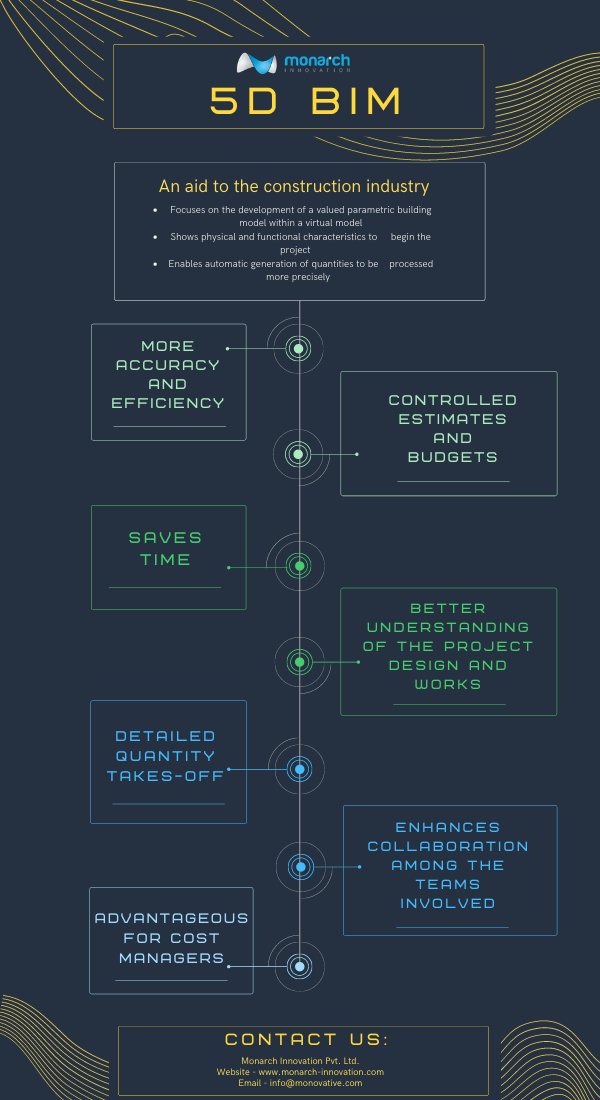
5D BIM modeling, 5-dimensional Building Information Modeling, is the extraction or development of a valued parametric building model within a virtual model. It visualizes a project that consists of budgetary and cost considerations associated with the project.  It is a five-dimensional plan showing the physical and functional aspects of any project. 5D BIM technology allows the involvement of more people in the conversation from the onset instead of working in isolation waiting to provide information about their piece of the project when it is time. It automatically generates accurate data and estimates costs for construction projects. 5D is productive in all aspects of the construction industry but the ones who are most benefited from this extra dimension are the project managers.

5D technology involves the extraction of quantities from the BIM model and aims to help the site team to manage the material resources based on the master project schedule. The extracted quantities are later used to generate a material management sheet. The sheet aids in extracting exact quantities of the materials based on the master project schedule. The team can extract the material quantity from any given time frame in the project cycle. It really helps in the reduction of the project waste since there will be no material dumping required on-site and an exact quantity of material can be ordered.

5D Macro BIM is the artistic form of design with the strategic function of a building’s architecture, and also increases transparency in the process. With 5D Macro BIM, one can easily model, design, and implement creative design concepts, clever exterior finishes, innovation layouts, uniquely shaped and aligned departments and floors in varying sizes. 5D Macro BIM modeling allows every element from square footage to pricing, timing, layouts, and more to be conceptualized. Using a BIM in the 5D approach allows a strong vision to crystalize early in the process so that a building’s element and detail align with big picture goals. Under the proper guidance of a full project team and estimation experts, owners can come up with informed decisions and be confident of getting the right facilities. It allows for greater participation in the design process. It has been very helpful in healthcare construction settings because it delivers more nuanced insights to owners to balance a facility function, cost, and ease of use for patients and visitors. For Example, A hospital in Texas wanted three different departments to be located on the ground floor.  Designers easily clicked and dragged color-coded sections of the designs to denote each department, shrinking or enlarging them based on the suggestions. These changes produced real-time shifts in the projected cost. For example, Korte designers helped the owner of a new healthcare facility in North Carolina to decide how to maximize finite resources by isolating individual floors in the design to examine the varying costs. This proved to be helpful in minimizing expenses in some places to allow more investment in others.

BIM software can affect the construction management process powerfully when it comes to cost-related information. With its aid, data connected to cost care are updated continuously with the progress of the project, i.e, the cost is dynamically evolved and readjusted rather than being solely defined at the beginning of the project. This makes it easier for the project managers to keep a track of the changes while keeping the project running within the agreed budget. It may be successful in improving cost prediction and resource management.

BENEFITS OF BIM

  • It improves onsite collaboration and communication. BIM association with several designing tools like Autodesk’s BIM 360 enables it to be smoother across different areas in the project. With cloud-based tools such as Autodesk’s BIM 360, Its ecosystem allows the team to share project models and coordinate planning, ensuring all design stakeholders have insight into the project. With cloud access, there’s no inconvenience to take the office to the field. With apps such as Autodesk’s BIM 360 tools, drawings and models can be viewed onsite on their devices, ensuring they have access to up-to-date project information at any time.
  • Model-based cost information – Including estimators earlier in the planning stage allows for more effective construction cost estimation that leads to the growth of model-based cost estimating. Using BIM tools such as Autodesk’s Revit reduces time consumption and allows estimators to focus on higher-value factors like identifying construction assemblies and factoring risks.
  • Visualization of projects in preconstruction – By using BIM, one can plan and visualize the entire project before the construction work is initiated. Space use simulations and 3D visualizations give an idea of how space will look like and also offers the ability to make changes before the construction work is initiated.
  • It increases productivity and prefabrication. It can be used to generate production drawings and databases for manufacturing purposes, allowing for prefabrication and modular technology uses. By designing, detailing, and building offsite in a controlled environment, one can diminish waste, increase efficiency, and reduce labor and material costs.
  • It can improve construction safety by highlighting the dangers before they act as problems and avoid physical risk by visualizing and planning site logistics beforehand.
  • It helps in the reduction of the amount of rework needed on a given job by avoiding clashes. One gets the opportunity of planning things in a proper manner to avoid last-minute changes.

BENEFITS OF 5D BIM

5D BIM
  • More accuracy and efficiency- decreases manual efforts with evaluating assets and computing costs while additionally reducing errors.
  • Gain complete control over project cost estimates and budget.
  • With 5D BIM, it becomes easier to recognize, evaluate and record any changes made in the models.
  • Saves time- provides shorter execution life cycles and saves time from documentation to material costs with accurate data unnecessary wastage and clashes are eliminated leading to shorter project execution life cycle.
  • A better understanding of the project design and cost drivers. The project team will have a concise and accurate description of scope costs and budgets.
  • Frees cost managers from tedious and time-consuming manual qualification.
  • Will also allow engineers and architects to experiment with innovative workplace design.
  • 5D BIM makes maintenance operations easier and increases gross productivity.
  • Helps in predicting the rough life of the building and analyzing which materials in the building could be used after demolition.
  • It enhances collaboration between teams involved in construction.
  • Detailed quantity takeoffs- as estimators spend most of their time in creating quantity takeoffs, 5D implementation paves the way for automation of the development of quantity take-offs. This helps in saving time which can be used by estimators in several areas like generating pricing models or accessing financial risks.
  • BIM allows all the stakeholders to work on a single model from various locations and devices. All skateboarders can work simultaneously and make changes together to augment the collaboration process.

BENEFITS OF 5D MACRO BIM

  • BIM allows all the stakeholders to work on a single model from various locations and devices. All skateboarders can work simultaneously and make changes together to augment the collaboration process.
  • Macro BIM features allow individual investors and real estate developers to evaluate the practicality and costs of building the project on a construction site.
  • Macro BIM focuses on construction site requirements and large-scale building massing. The value of macro bim models accrues over time and across projects using the large data sets that are increasingly available.

WHAT DOES BIM MEAN FOR THE COST MANAGERS?

5D BIM is a strong tool for cost managers. It adds much more flexibility to work and improves their

decision making process. 5D cost managers have the benefit of re-estimating the developing design for

infinite times and can give feedback accordingly on the estimated variances and corrective suggestions.

Cost managers can very quickly determine the quantity of a particular component, applying rates to several quantities to provide an overall estimate for the package.

Cost managers can forecast estimations and update design teams with feedback for various project stages. As cost managers have an in-depth view of what items needed to go onsite, material logistics can be planned accordingly. 5D cost estimation helps cost managers to get precise construction costs and estimates. It also provides shorter project cycles and saves construction time.

SCOPE

Data connected to costs are continuously updated as the project progresses. This 5D BIM makes.

project managers to monitor changes while keeping the project running within the agreed budget. This can improve cost predictability and resource management. Applications supporting BIM in android and ios will help contractors designers and the AEC industry, in general, to constantly keep a check on the developing designs of the model and apply corrections immediately creating a better commutation with the skateboarders of the project involved. The cost estimation will allow clients to visualize the impact of changes in the design and timeline on project costs. This will help reduce delivery time, enhance quality control, eliminate budget overruns and add significant value to a project.

Monarch Innovation has been fulfilled the needs of the construction industry with customized and standard solutions irrespective of size and project status whether residential, industrial retail, healthcare, or education. Contact Us for more information.

Previous Next
Close
Test Caption
Test Description goes like this
Add to cart
Open chat
Hello,
Welcome to Monarch Innovation!

How Can I Help You..?