Types of Construction Drawings

46 Major Types of Construction Drawings Used in Building Construction

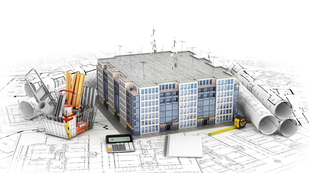
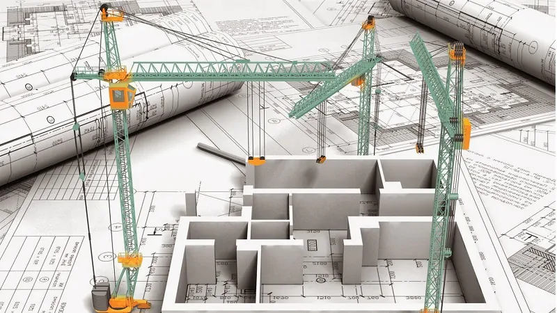
Construction drawings are used for a wide variety of reasons and applications in construction and architectural projects and activities.

What is a construction drawing?

It is a graphical representation of what will be built, how it will be laid out, the components, framework, and dimensions. There is a construction drawing highlighting the details of every aspect of a construction project.

Construction Drawings including each of its subtypes are helpful to different groups of workforce assigned with doing or overlooking the various tasks that make up a construction project.

How are construction drawings made?

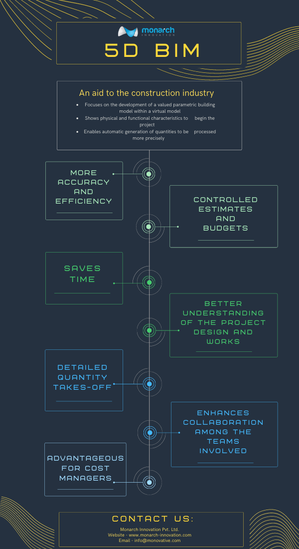
Rarely are construction plans drawn by hand anymore. They are either sketched and rendered using computer-aided drafting such as computer-aided design (CAD) software. And in recent times, Building Information Modeling (BIM) software has made it easy to render and visualize in detail the virtual construction models (VCM).

To know more about BIM services, budgeting, and how they can benefit your project, reach out to us at Monarch Innovation for all queries, assistance, and collaborations.

Top 46 most common types of Construction drawings use regularly in construction industries.

Architectural Drawings

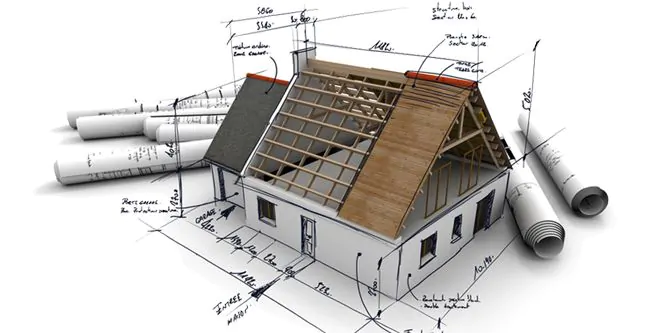
Architectural Drawings are drawing work that is used in building drawings to depict the dimensions, depth, and layout of the actual building, prior to beginning the construction. Architectural Drawings act as a blueprint construction, drawn to scale, to help the engineers visualize the project.

Various types of Architectural Drawings commonly used are:
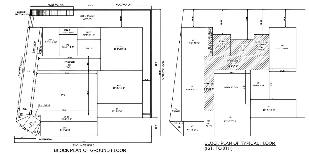
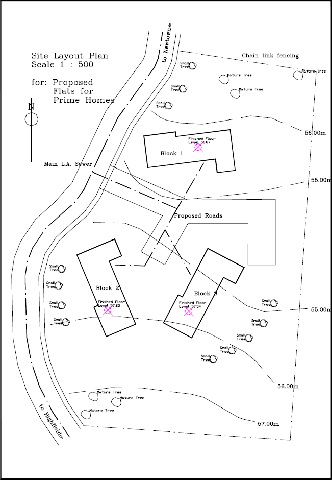
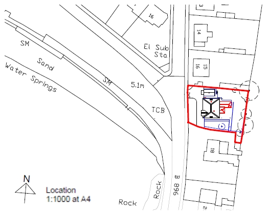
1. Block Plan

This drawing gives a layout of the site or the buildings in the surrounding area, laid out on a map drawn to scale.

  • It gives a firsthand idea of the roads, boundaries and other such details that are necessary to understand where your construction site lies.
  • It helps the person dealing with your construction plan or project request to understand what and where you are proposing it and help you out with it too.
  • Block plans are made in relation to Ordnance Survey Maps and the recommended scales used are 1:2500, 1:1250 or 1:500.
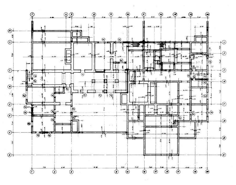
    Block Plan Construction Drawing

2. Foundation plan 

Not to be mistaken for just the ground or basement floor plan. Foundation Plans are drawing work to render any of the floors of the building being constructed. They help visualize the dimension, size, shape, height and configuration of rooms/stairs/landings with each other.
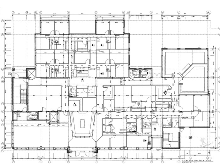
Foundation Plan Construction Drawing
Foundation Plan

3. Floor plans

In-depth rendering of the layout of the rooms for each floor. It describes in 2D the orientation of rooms and components to each other. Floor plans may or may not be utilized in commercial or non-commercial building projects, but it is necessarily still made as part of the drawing work.


floor plan designed building drawing
Floor plan designed building drawing

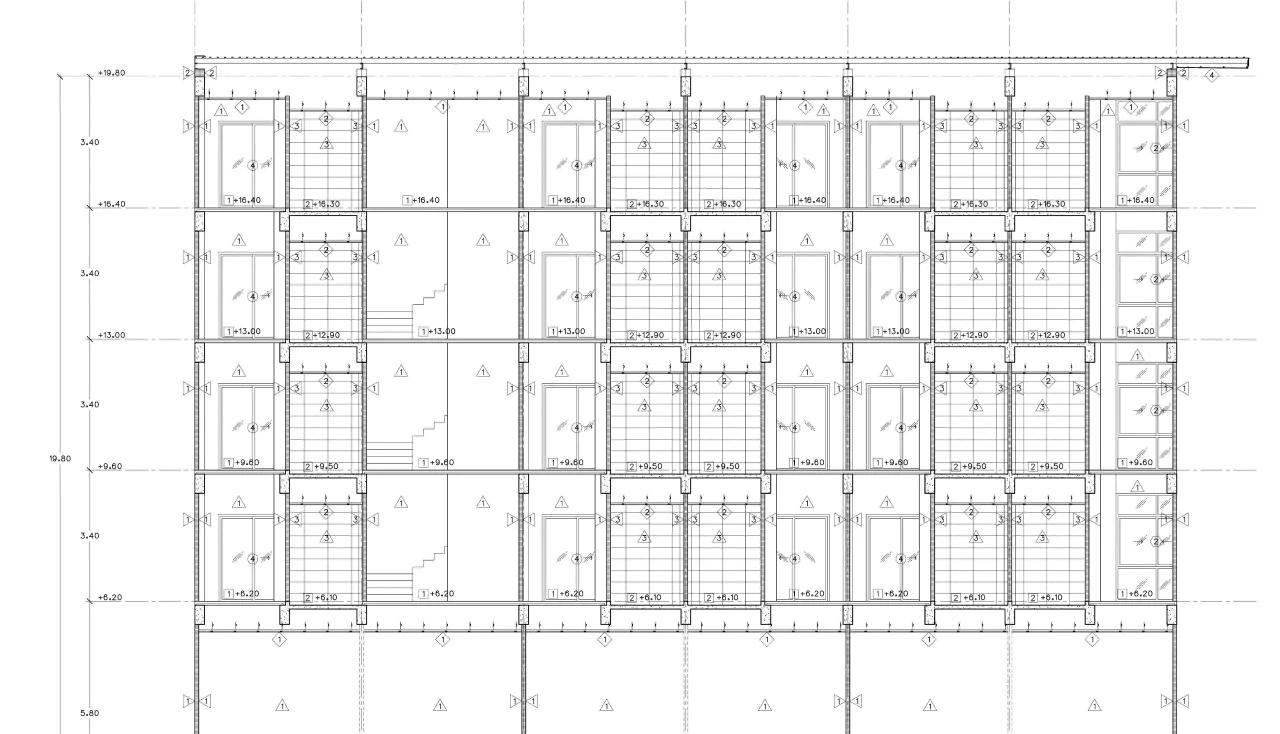
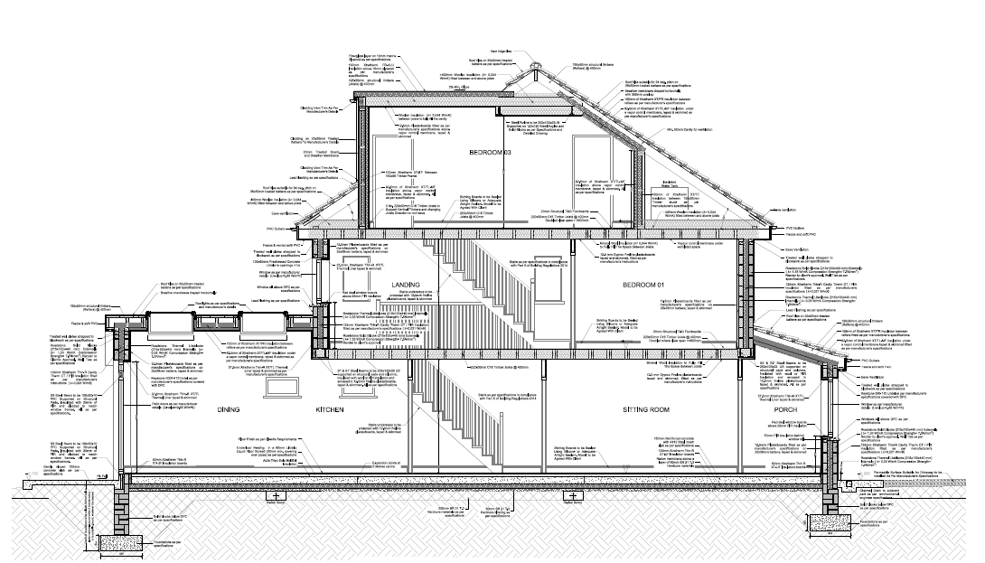
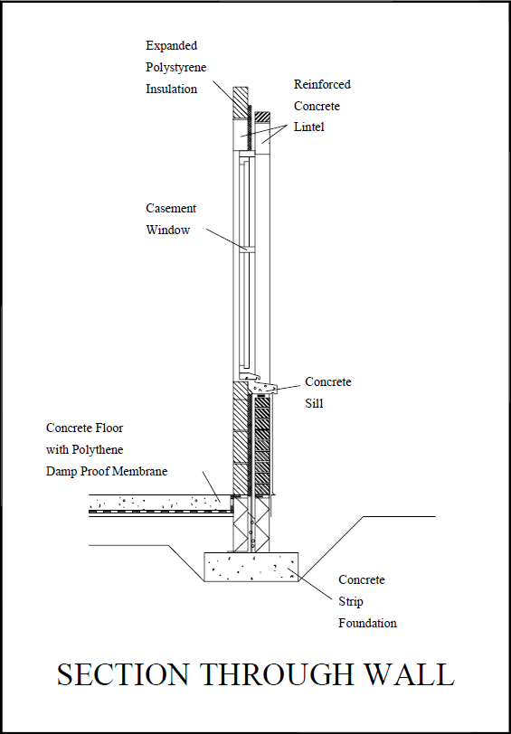
4. Sectional Drawings

These are drawings that depict a part or whole of the framework in sliced form. It helps understand the measurements of various building components with each other, the materials used in the construction of those components, the height, depth, and hollowness, etc.

Sectional Drawing
Sectional Drawing

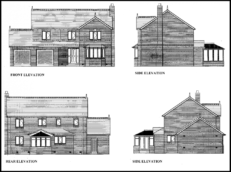
5. Elevation Drawings 

These architectural drawings offer an aesthetic overview of the various components of the building such as columns, windows, and doorframes. It also helps understand the relative surface, internal markings, and relative height of these different components to each other.
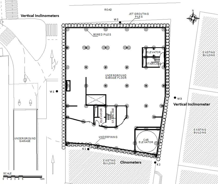
Typical elevations drawing
Elevations Drawing https://www.designingbuildings.co.uk/

6. Site Plan 

A site plan is a detailed drawing that shows the entire construction site with property boundaries, existing structures, proposed new building locations, site grading/topography, and other site features like landscaping, parking areas, utilities, etc.

Typical Site Plan
Typical Site Plan https://www.designingbuildings.co.uk/

7. Isometric Drawing

An isometric drawing is a type of 3D parallel projection used to represent objects pictorially. It shows three sides of an object with the vertical lines projecting at a 30-degree angle and the horizontal lines projecting at a 30-degree angle.

8. Axonometric Drawings

Axonometric drawings are types of 3D parallel projections that show an object in an oblique/angled view. They include isometric, dimetric, and trimetric drawings depending on the exact angle used for the horizontal and vertical lines.

9. Presentation Drawings

Presentation drawings are highly detailed renderings or 3D models used to communicate and visualize the design intent for clients, stakeholders, and approving authorities. They showcase the appearance, materials, and aesthetic qualities of the project.

10. Survey Drawings

Survey drawings represent the existing conditions on a construction site based on detailed field survey data. They show site topography, boundaries, existing structures, underground utilities, and other existing features crucial for planning new construction.

11. Location Drawings

Location drawings are used to indicate the specific position or location of building components, systems like HVAC ducts, plumbing pipes, electrical conduits, etc. within the overall construction. They help avoid conflicts during installation.

12. Assembly Drawings 

Assembly drawings illustrate in detail how different components and materials fit together during construction. They provide crucial information on the sequence, connections, and relationships between various building parts to guide proper assembly.

Assembly drawing
Assembly Drawing https://www.designingbuildings.co.uk/

13. Parametric Drawing

A parametric drawing is created using parametric modeling software that allows the drawing views to automatically update when design parameters like dimensions or specifications are changed. This ensures consistent, coordinated drawings across all sheets.

14. Design Drawing

Design drawings are conceptual drawings that architects create early in the design process to explore, develop, and communicate design ideas and concepts to clients before moving to more detailed stages. They convey the building’s overall form, massing, and character.

15. Reflected Ceiling Plan

A reflected ceiling plan is a drawing that shows the layout of the ceiling as if it’s viewed from above by someone standing in the room looking upwards. It depicts ceiling-mounted elements like light fixtures, diffusers, speakers, etc.

16. Record / As-built Drawings

Record drawings, also called as-built drawings, are the final set of drawings updated to incorporate all the construction changes, modifications, and as-built conditions from the actual construction process. They document the constructed project accurately.

House floor plan featuring kitchen and living room. As-built Drawings
As-built Drawings https://www.designingbuildings.co.uk/

Structural Drawings

Structural Drawings also serve as civil engineering drawings. They are useful in understanding the physical nitty-gritty of a building framework. They act as a structural design guide for the workers and on-site engineers. Common types of structural drawings are:

17. General Note

An overview of all the codes, procedures, and abbreviations, etc required to give a comprehensive guide to getting to work on the construction site. This includes concrete mix, details for other structural drawings, lengths and construction types of each component, etc.

18. Excavation Drawing

This civil engineering drawing describes the dimensions and positions for the excavation process prior to the actual building work. It covers details like tunneling, shafts, removal of soil, grid plans, etc. required to start the groundwork.

19. Column Layouts

These structural drawings include the layouts of the way columns will be laid out. It makes it easier for contractors to plan the layout of the building and start the process by identifying the position and distance between columns across the floor.

20. Beam Layouts

It includes all the beam-like structures, such as the ones supporting the roof and the windows, or the beams used for strengthening purposes. They are designed for each floor and cover the length, height, material, etc.

21. Roof slab layouts

this civil engineering drawing describes the exact dimensions of all the slabs required for roofs or slants. It can be designed over AutoCAD software as it requires precision and data.

22. Section Plan

A section plan is a drawing that shows a cross-sectional vertical or horizontal view through the building by cutting through it. Section plans clarify the internal construction, framing and relationships between different structural elements.

23. Detail Drawings

Detail drawings are large-scale drawings focused on specific construction details and connections between different structural components. They provide in-depth, magnified information crucial for installation and assembly by showing reinforcements, fasteners, dimensions, etc.

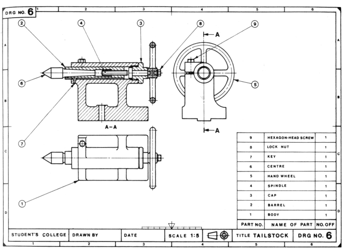
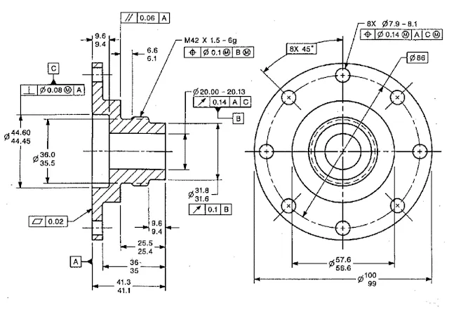
25. Component Drawing

Component drawings focus on providing comprehensive details and dimensions of individual structural elements like beams, columns, footings, etc. They serve as a reference for manufacturing, fabrication, or on-site construction of these components.

Typical Component Drawing
Component Drawing https://www.designingbuildings.co.uk/

26. Column Layout

A column layout plan indicates the locations of all structural columns in the building along with the column gridlines and dimensions. It helps ensure proper positioning and installation of columns during construction.

27. Plinth Beam Layout

The plinth beam layout plan shows the layout, positions and dimensions of all plinth beams or grade beams that will be constructed below and support the load-bearing walls at the foundation level.

28. Lintel Beam Layout

A lintel beam layout plan depicts the locations, sizes and geometry of all lintel beams provided over wall openings like doors, windows, etc. to transfer loads across those openings safely.

29. Roof Beam Layout / Shuttering

The roof beam layout plan shows the framing layout for supporting the roof structure with dimensions for beam sizes and spacing. The shuttering layout indicates formwork patterns/positioning for concrete roofs.

30. Framing Plan

A framing plan is a structural drawing that illustrates all the load bearing, framed elements in the building like floors, walls, and roofs. It clarifies the overall framing system, member sizes, connections, and relationships.

31. Engineering Drawing

An engineering drawing is a technical drawing produced by structural engineers with precise dimensions, calculations and specifications related to the building’s structural design, analysis and detailing following relevant engineering codes.

Engineering Drawing
Engineering Drawing

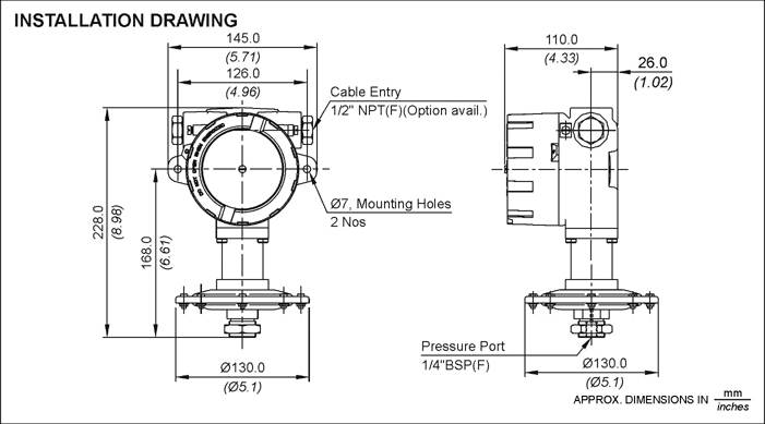
32. Installation Drawings

Installation drawings provide clear instructions and details guiding the installation processes for prefabricated structural components or building systems manufactured off-site for easy assembly on the construction site as per design specifications.

Typical Installation Drawing
Installation Drawing https://www.designingbuildings.co.uk/

MEP Drawings

33. Electrical drawings

Most residential construction drawings or commercial construction drawings require a functional outline of the number of power outlets, light fixtures, fan fixtures, etc. They also include the wiring pattern and details about the electrical load it can carry. Common details included in Electrical Drawings are:

  • Earthing layout
  • Light fixture layout
  • Generator and other equipment
  • Cable tray layout
  • Hazardous area classifications
  • Lighting protection system

    Electrical drawings
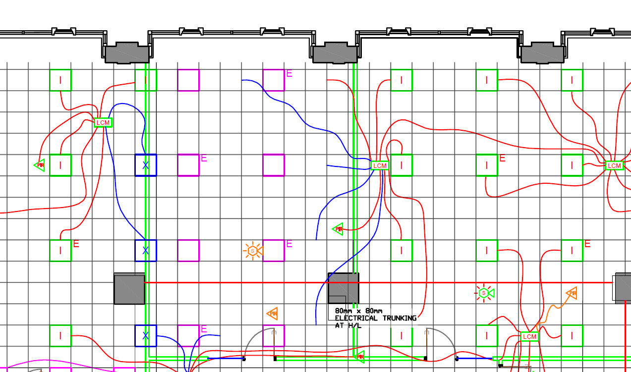
    Electrical drawings https://www.designingbuildings.co.uk/

    34. Plumbing Drawings

Just like electrical layouts, plumbing is another part of any residential or commercial construction drawing that marks the points where plumbing components need to be set up. Space is left here accordingly for further pipe and sanitary ware fixtures to be added once the structural component is finished. Plumbing drawings commonly include:

  • Pipes – water pipes, drainage pipes, internal pipes
  • Material of pipes
  • Outlet points – taps, sinks, tanks etc
  • Position and location of pipes and outlets

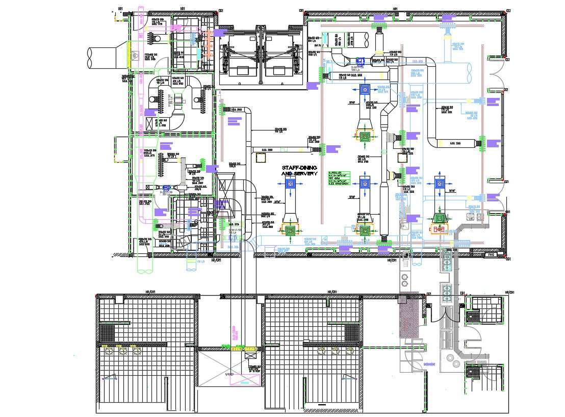
    35. HVAC/Mechanical Drawings

These are known as mechanical construction drawings. They provide details and a design framework for heating and ventilation systems in a building. Central heating/cooling, air conditioning vents, ventilators, etc are all included according to the need and site of the building plans. Builders use these design constructs in their process accordingly.

Hospital Building HVAC Duct Design Layout Plan
HVAC Drawing https://thumb.cadbull.com/

36. Piping Spool Drawings

Piping spool drawings are detailed drawings focused on specific prefabricated sections of pipes called spools used in industrial piping systems. They show precise dimensions, connections, and routing of these spool sections.

37. Firefighting Drawings

In today’s construction systems, safety design is paramount. Firefight Drawings are also a part of blueprint drawings of a building that allocate points for fire hoses, fire escapes, water outlets, sandbags, or any other fire safety equipment required by the regulatory body overseeing the project.

Additional Drawing Types

38. Production Drawings

These Construction Drawings are used to convey functional information to the workers and engineers on site. It describes the materials, the assembly of various parts, the tools required, the dimensions, and other information required during the process. It may also include additional information or an infographic on how to meet those set requirements.

Production Drawings
Production Drawings https://miro.medium.com/


39. Environmental Plans

Making sure environmental guidelines and management is properly followed is a part of construction projects that cannot be overlooked. The aim is to minimize environmental damage and future negative impacts of the construction project. It includes measures like:

  • Chemical disposal mechanisms
  • Management of erosion and sedimentation
  • Outlining environmental guideline compliance measures
  • Measures to handle accidents and emergencies like fire

    40. Finishing Drawings

These include finer and more detailed plans of the building after the whole structural and architectural framework has been set up. These are required for the aesthetic and functional value of the building. These construction drawings include details of:

  • Tile patterns,
  • Floor patterns
  • False ceilings
  • Paint colors and textures
  • Plaster
  • Woodwork
  • Motifs and designs

41. Location Plan

A location plan is a simple drawing that shows the location of the construction project site about its surroundings like nearby roads, landmarks, neighborhoods etc. to help identify and access the site easily.

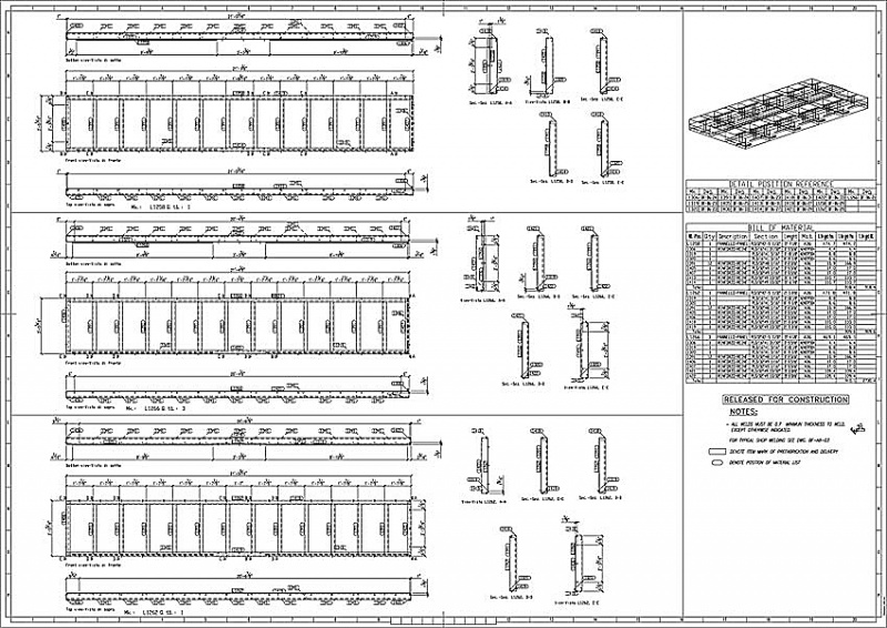
42. Shop Drawings / Fabrication Drawings

Shop drawings or fabrication drawings provide precise dimensions, details, and instructions from the manufacturers/suppliers for prefabricated construction components, materials, or equipment off-site before delivery to the construction site for installation.

Shop Drawings
Shop Drawings https://www.designingbuildings.co.uk/

43. Scale Drawings

Scale drawings refer to any plans, sections, elevations, or detail drawings that are produced using precise measurement scales to represent actual dimensions accurately, allowing dimensions to be determined from the drawings reliably.

Scale Drawings
Scale Drawings https://www.designingbuildings.co.uk/

44. Perspective Drawings

Perspective drawings are three-dimensional views or illustrations drawn to show depth and provide a view of the subject from a particular vantage point as it would appear to the human eye.

45. Working Drawings

Working drawings comprise the complete set of finalised technical drawings including plans, sections, elevations, and details issued to construction crews on site with all required information for executing the building construction work as per the design.

Working Drawings
Working Drawing https://www.designingbuildings.co.uk/

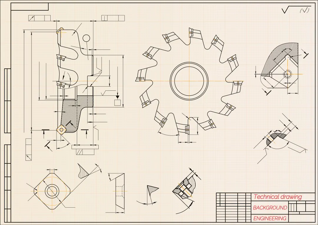
46. Technical Drawings

Technical drawings are a general term encompassing all types of precise drawings used to convey technical or engineering information about an object, product, system or structure through illustrations, dimensions, notes, symbols, and conventions.

Technical Drawings
Technical Drawings

To get professional advice and assistance on your construction projects, contact us at Monarch Innovation for our host of BIM, Building Design, and Mechanical Engineering services.

Backed up by experience in this field, we would be happy to help you get insights, in-depth analysis, and coordinate your project plans to make the process hassle-free.

FAQs


What are construction drawings?

Construction Drawings are a graphical representation of what will be built, how it will be laid out, the components, framework and dimensions. There is a construction drawing highlighting the details for every aspect of a construction project.

What are the different types of construction drawings?

Below are the set of basic drawings included in Construction drawings:
1. Elevation drawings – These drawings offer an overview of the individual components that make up the structure, plus the structure as a whole.
2. Sections – Sections are slices of the building, to showcase the inner dimensions.
3. Floor Plans – The rendering of each of the floors in a building, which lays out the rooms, the doors, the positioning of the stairs, windows, columns, kitchen, slabs, etc all in 1D. It helps one to understand the orientation of the rooms and other physical structures that make up the floor.
4. Details – As the name suggests, these are drawings that focus more on individual components of a building, in detail.

What are architectural construction drawings?


Architectural Construction Drawings are drawing work that is used in building drawings to depict the dimensions, depth and layout of the actual building, prior to beginning the construction. Architectural Drawings act as a blueprint construction, drawn to scale, to help the engineers visualize the project.

How to make construction drawings?


Construction drawings usually include a set of working drawings that cover different aspects of the project plan. These drawings usually comprise Elevation drawings, Floor Plans, Sections and Detail Drawings.

5D BIM Plan

5D BIM: How it will Help the Construction Industry

5D BIM (Building Information Modelling) is a highly effective system that helps plan and execute real construction through a digital look of a physical structure. It is an intelligent model-based process that connects AEC professionals so that they can design, build and operate buildings and infrastructure more efficiently. It goes further than just the building’s physical appearance and includes information about every component that goes into a project. This helps the designers, whether an architect, an engineer or a construction drawings professional, to create and design more efficiently as compared to other tools in the market today.

BIM is a process of creating information models formed of graphical and non-graphical information in a shared digital space known as a common data environment (CDE).  The BIM process helps in planning the project stages, components, and construction expenses.  When an information model is created, scheduling data can be added to different components generating accurate program data for the project, this is 4D BIM. The next step involves producing accurate cost estimates from the components of the information model, this process is termed 5D BIM.

BIM OBJECTS:- There are primarily two types of BIM objects –

  • Component: The component objects are mainly the building products that have fixed geometrical shapes such as windows, doors, boilers, etc.
  • Layered: The layered objects are the building products having no fixed shape or size such as roofing, walls, and ceilings.

BIM objects may be categorized under –

  • Generic: These objects, often referred to as library objects, are used during the beginning phase of designing as a visual expression for a specific object to be selected at a later stage.
  • Specific: These objects, often termed manufacturer objects, are used to represent a manufacturer’s specific products.

BIM objects are available in a range of file formats that are suitable for use in software like Bentley ACEOsim, Graphisoft ArchiCAD, Revit Architecture, and Nemetschek Vectorworks.

There are certain places where one can expect the availability of BIM objects. NBS National BIM Library is one of the library sites where one can find BIM objects. It serves as an online environment that is created to store BIM model files. In the case of the NBS National BIM Library, all BIM objects are authorized to NBS standards. It ensures the user is able to select and use BIM objects that are compatible across all the working platforms.

5D BIM modeling, 5-dimensional Building Information Modeling, is the extraction or development of a valued parametric building model within a virtual model. It visualizes a project that consists of budgetary and cost considerations associated with the project.  It is a five-dimensional plan showing the physical and functional aspects of any project. 5D BIM technology allows the involvement of more people in the conversation from the onset instead of working in isolation waiting to provide information about their piece of the project when it is time. It automatically generates accurate data and estimates costs for construction projects. 5D is productive in all aspects of the construction industry but the ones who are most benefited from this extra dimension are the project managers.

5D technology involves the extraction of quantities from the BIM model and aims to help the site team to manage the material resources based on the master project schedule. The extracted quantities are later used to generate a material management sheet. The sheet aids in extracting exact quantities of the materials based on the master project schedule. The team can extract the material quantity from any given time frame in the project cycle. It really helps in the reduction of the project waste since there will be no material dumping required on-site and an exact quantity of material can be ordered.

5D Macro BIM is the artistic form of design with the strategic function of a building’s architecture, and also increases transparency in the process. With 5D Macro BIM, one can easily model, design, and implement creative design concepts, clever exterior finishes, innovation layouts, uniquely shaped and aligned departments and floors in varying sizes. 5D Macro BIM modeling allows every element from square footage to pricing, timing, layouts, and more to be conceptualized. Using a BIM in the 5D approach allows a strong vision to crystalize early in the process so that a building’s element and detail align with big picture goals. Under the proper guidance of a full project team and estimation experts, owners can come up with informed decisions and be confident of getting the right facilities. It allows for greater participation in the design process. It has been very helpful in healthcare construction settings because it delivers more nuanced insights to owners to balance a facility function, cost, and ease of use for patients and visitors. For Example, A hospital in Texas wanted three different departments to be located on the ground floor.  Designers easily clicked and dragged color-coded sections of the designs to denote each department, shrinking or enlarging them based on the suggestions. These changes produced real-time shifts in the projected cost. For example, Korte designers helped the owner of a new healthcare facility in North Carolina to decide how to maximize finite resources by isolating individual floors in the design to examine the varying costs. This proved to be helpful in minimizing expenses in some places to allow more investment in others.

BIM software can affect the construction management process powerfully when it comes to cost-related information. With its aid, data connected to cost care are updated continuously with the progress of the project, i.e, the cost is dynamically evolved and readjusted rather than being solely defined at the beginning of the project. This makes it easier for the project managers to keep a track of the changes while keeping the project running within the agreed budget. It may be successful in improving cost prediction and resource management.

BENEFITS OF BIM

  • It improves onsite collaboration and communication. BIM association with several designing tools like Autodesk’s BIM 360 enables it to be smoother across different areas in the project. With cloud-based tools such as Autodesk’s BIM 360, Its ecosystem allows the team to share project models and coordinate planning, ensuring all design stakeholders have insight into the project. With cloud access, there’s no inconvenience to take the office to the field. With apps such as Autodesk’s BIM 360 tools, drawings and models can be viewed onsite on their devices, ensuring they have access to up-to-date project information at any time.
  • Model-based cost information – Including estimators earlier in the planning stage allows for more effective construction cost estimation that leads to the growth of model-based cost estimating. Using BIM tools such as Autodesk’s Revit reduces time consumption and allows estimators to focus on higher-value factors like identifying construction assemblies and factoring risks.
  • Visualization of projects in preconstruction – By using BIM, one can plan and visualize the entire project before the construction work is initiated. Space use simulations and 3D visualizations give an idea of how space will look like and also offers the ability to make changes before the construction work is initiated.
  • It increases productivity and prefabrication. It can be used to generate production drawings and databases for manufacturing purposes, allowing for prefabrication and modular technology uses. By designing, detailing, and building offsite in a controlled environment, one can diminish waste, increase efficiency, and reduce labor and material costs.
  • It can improve construction safety by highlighting the dangers before they act as problems and avoid physical risk by visualizing and planning site logistics beforehand.
  • It helps in the reduction of the amount of rework needed on a given job by avoiding clashes. One gets the opportunity of planning things in a proper manner to avoid last-minute changes.

BENEFITS OF 5D BIM

5D BIM
  • More accuracy and efficiency- decreases manual efforts with evaluating assets and computing costs while additionally reducing errors.
  • Gain complete control over project cost estimates and budget.
  • With 5D BIM, it becomes easier to recognize, evaluate and record any changes made in the models.
  • Saves time- provides shorter execution life cycles and saves time from documentation to material costs with accurate data unnecessary wastage and clashes are eliminated leading to shorter project execution life cycle.
  • A better understanding of the project design and cost drivers. The project team will have a concise and accurate description of scope costs and budgets.
  • Frees cost managers from tedious and time-consuming manual qualification.
  • Will also allow engineers and architects to experiment with innovative workplace design.
  • 5D BIM makes maintenance operations easier and increases gross productivity.
  • Helps in predicting the rough life of the building and analyzing which materials in the building could be used after demolition.
  • It enhances collaboration between teams involved in construction.
  • Detailed quantity takeoffs- as estimators spend most of their time in creating quantity takeoffs, 5D implementation paves the way for automation of the development of quantity take-offs. This helps in saving time which can be used by estimators in several areas like generating pricing models or accessing financial risks.
  • BIM allows all the stakeholders to work on a single model from various locations and devices. All skateboarders can work simultaneously and make changes together to augment the collaboration process.

BENEFITS OF 5D MACRO BIM

  • BIM allows all the stakeholders to work on a single model from various locations and devices. All skateboarders can work simultaneously and make changes together to augment the collaboration process.
  • Macro BIM features allow individual investors and real estate developers to evaluate the practicality and costs of building the project on a construction site.
  • Macro BIM focuses on construction site requirements and large-scale building massing. The value of macro bim models accrues over time and across projects using the large data sets that are increasingly available.

WHAT DOES BIM MEAN FOR THE COST MANAGERS?

5D BIM is a strong tool for cost managers. It adds much more flexibility to work and improves their

decision making process. 5D cost managers have the benefit of re-estimating the developing design for

infinite times and can give feedback accordingly on the estimated variances and corrective suggestions.

Cost managers can very quickly determine the quantity of a particular component, applying rates to several quantities to provide an overall estimate for the package.

Cost managers can forecast estimations and update design teams with feedback for various project stages. As cost managers have an in-depth view of what items needed to go onsite, material logistics can be planned accordingly. 5D cost estimation helps cost managers to get precise construction costs and estimates. It also provides shorter project cycles and saves construction time.

SCOPE

Data connected to costs are continuously updated as the project progresses. This 5D BIM makes.

project managers to monitor changes while keeping the project running within the agreed budget. This can improve cost predictability and resource management. Applications supporting BIM in android and ios will help contractors designers and the AEC industry, in general, to constantly keep a check on the developing designs of the model and apply corrections immediately creating a better commutation with the skateboarders of the project involved. The cost estimation will allow clients to visualize the impact of changes in the design and timeline on project costs. This will help reduce delivery time, enhance quality control, eliminate budget overruns and add significant value to a project.

Monarch Innovation has been fulfilled the needs of the construction industry with customized and standard solutions irrespective of size and project status whether residential, industrial retail, healthcare, or education. Contact Us for more information.

Mechanical Drafting

The Importance of Mechanical Drafting for Emerging Architects

What is one thing modern architects and designers are giving up entirely? The answer is mechanical drawing and drafting skills. It is no doubt the 21st century, and we are living and breathing technology. Digitalization and software skills are ruling the roost for efficiency and adaptability.

However, what any good architect or senior associate with let you know is that communication is the bedrock of your design, apart from the foundations that you draw for your building of course. As young mechanical artists, most of the students have rarely, if ever drawn by hand. Computer and iPads having drawing and visualization software and versatile stylus have made it even easier to have designed on your digital fingertips.

What we have to consider as emerging Architects is that without hand drafting skills and practice, one is missing out on the tactile education that integrates design, elevations, angles and visualization skills into our subconscious mind.

Picture a scenario where you are in a meeting with a potential client in the Mechanical Design outsourcing company you work in. They have an idea in mind while you have some modification in your head, and both of you need to communicate the visual aspects of the design to reach a middle ground. And most of all, this is a crucial point where you can gain your client’s trust in your designing aptitude and eye for detail. In such a situation, you can quickly sketch out a draft of the visual in your head, giving a view from 2-3 angles, detailing the important components that the client was trying to understand, and negotiating all minor changes in the design that pops up on both your and the client’s head while looking at the sketch. This is not something you could have achieved with a moment’s notice on mechanical design software. Nor is it something that software can reproduce to give you credibility and value in your client’s eye. Your individuality and visualization power stand out when you draft a design by hand.

The Drawback in Computer-Aided Mechanical Designing

A computer can never replace the raw conceptualization and communication that an architect can render by hand. A computer-aided program like AutoCAD or mechanical CAD design services does make the design workflow easier and more detailed, but it makes the architect lose out on their integral drawing skill. Since any computer-aided mechanical drafting software can make it easy to integrate changes or load templates, it is easy to give in to the comfort of not having to conceptualize and draw a design by hand. The designer loses their credibility.

Hand drafting is one of the quickest and surest ways to learn line drawing, understand perspectives, scale and establish a meaningful relationship with the creation you made on paper. Drawing by hand, feeling the hand flow around the paper, giving angles, shading, appreciating the space and scale without the luxury of scrolling out of frame. None of these is possible with computer-aided designing.

Emerging Architects and young intern architects should learn to appreciate and comprehend the basics that go into the building of a whole project. Starting small from drawing and understanding sectional drawings, elevations and sketching to pen down ideas is a great way to integrate design principles into the mind. Have you ever noticed how engineers or architects tend to draw at the back of an envelop or the back of the rough paper to explain small designs or concepts to others? This just shows how natural it feels to the brain to communicate design by hand.

One of the most important skills one needs in this trade is the ability to solve problems. When working in teams and peers, a young architect might not be able to develop their comprehension and conveying skills like their previous generation of architects. What computer-aided drafting software might not teach you is how to look at any object and instantly visualize and render it from all sides, elevations, sections and details.

Reasons why Mechanical Drafting is Important

Not just the technical skill of being able to draft mechanical drawings, engineers and architects are also taught communication of concepts by hand. Here is a breakdown of the technical and psychological reasons that drawing by hand should continue being an important part of the learning curve for young interns and emerging architects:

  1. Sketching/Drafting is a form of graphical representation that teach skills and service needs that are not developed when using computer-aided drafting entirely
  2. Drawing/Drafting is still the most preferred form of representing external data by senior associates and architects. The reason for it can be further understood as:
    • Diagrams preserve geographical and topographical information. It allows us to easily index and labels information that can help in the computation process
    • Mechanical drafts are able to group multiple subgroups of information into a single diagram and visual. It helps to understand the correlation of elements in the drawing and knowing how it will join to form the larger picture after computerization instead of leaving it entirely on the software itself.
    • Diagrams can use a large amount of perceptual information, that cannot be understood in detail if rendered directly on the software
  3. Drawing is a basic cognitive capability that an architect requires for mental stimulation, representation of data that he sees on a daily basis, externalizing the visual imagery that pops up in their mind when asked to think up solutions to a construction project.
  4. Mechanical drafting is required so that an architect can render the idea in their head to an external memory medium too. Transforming hand-drawn drafts into CAD design requires one to know the basics of how line drawing and scaling works. The cognitive skills or process underuse when drawing a line by hand is different than rendering a line on AutoCAD or other drafting software.
  5. Mechanical Drafting showcases the concept and cognitive ability of an architect, which is independent of their drawing’s characteristics. It builds trust in themselves and their clients when they can determine the design features required to bring an idea to life on paper, or later on a mechanical drafting software.

In conclusion

There is evidence in the research done, the experience and success stories of senior architects and designers, as well as in cognitive psychology that drawing by hand is important in shaping a sound, skillful and ready-to-take-on-challenges architect.

Drawings have always been the ideal way of representing data and components in any building or design process. And it cannot be denied that it plays an important role in the design process.

Mechanical drawings are the window to an Architect’s soul. It forms the basis of their problem-solving abilities and their communication powers. No matter how technology eases life ahead, any upcoming architect needs to be grounded to their roots of handmade mechanical drawings.

To know more about Construction Drawings, As-built drawings, their types, and uses, read our other blogs for the same. And if you have an upcoming construction project that you want to be streamlined, Contact us at Monarch Innovation. Our suite of BIM solutions and our professional team of Engineers and Designers will take on the challenge and deliver it within your desired budget.

What are As-Built drawings in the Construction Industry?

As-Built Drawings

There is rarely ever a situation where the blueprint drawings on paper match the real-world structure exactly the way it was designed. As-Built drawings reflect the actual structure or space that gets built.

As-Built drawings are drawing records that reflect the changes made during the entire construction process of a project. They say a picture speaks a thousand words – And in any construction project, there is no better way of keeping updated track of the multiple parallel steps than As-Built drawings.

According to Business Dictionary, As-Builts are a “revised set of drawings that reflect all changes made in the specifications and working drawings during the construction process. It shows the exact dimensions, geometry and location of all elements of the work completed under the contract.”

These drawings are usually addressed by the contractor at the end of the project. As-Built drawings are an essential component in the lifecycle of the project but they tend to get overlooked until the very end because way too many steps and changes need to be recorded. This might lead to lapses in the final project looking exactly like how it was initially planned to be.

In this article we get into the details of why As-Built drawings are important, who designs them, who can manage and access the data, how should they be utilized, and what effective strategies to make the best use of As-Built drawings in the construction industry.

For more knowledge and professional guidance on how to set up and manage your As-Built plans for your construction project, reach out to us at Monarch Innovation.

Who are As-Built drawings created by?

The architects and designers who are responsible for the framework and detailing of the entire project are best equipped to create As-Built drawings. Once created and maintained by architects/designers, it is then managed by the contractor on site. It makes sure that the construction drawings and resources do not merely exist in the original blueprints drafted, but beyond the lifespan of the project too.

Even if ownership of the project changes or the set of employees are replaced in the duration of the project, the As-Built drawings help in getting familiar and keeping track of the progress in the plans. Any future modifications or new construction can be continued on top of the work already accomplished.

What do As-Built drawings need to include?

There is no standard on what should be the expected output of an As-Built plan. It varies in the eyes of various contractors depending on the expectations they have from the data in the As-Built construction. To make the progress on the project clear and useful, As-Builts can include certain details such as:

  • Record the scale measurements used in original drawing constructions, and further changes made to it, if any.
  • Include changes made to length, dimensions, orientations, fabrications or location of any component of the construction process
  • Making note of the date when changes are made
  • Making note of any obstacles in the execution of original blueprints, and what was the solution made in place of it
  • Include original shop drawings and record any changes made to them
  • Any additional work done on the project that is extra to the originally planned drawing construction

Why are As-Built Drawings important in the Construction Industry?

As-Built construction plans are important at each step of the way and to each of the shareholders in the process from start to end. Here’s how:

  • Contractors require As-Built drawings to record the transition from one phase of the construction to the next. They can then visualize the steps needed to take further, and issue actions to the workers accordingly.
  • If obstacles or issues occur during the construction process, As-Builts can be referred to identify the last step and resolve it
  • If constantly being updated, As-Built drawings help identify foreseeable complications and can be resolved before they happen.
  • Owners or clients of the property can refer to the As-Built documentation to check for the installations or designs being included, and ask to modify them if they face any issues with it.
  • Property buyers need As-Built drawings to understand what exactly they are buying or selling. They can also use it as the basis of any future renovations and installations.
  • The renovation process is made easy when the detail of what is already done is available. It saves expenses incurred in learning about the existing setup before making additional changes.

Traditional vs. BIM As-Built Construction

The traditional method of maintaining As-Built drawings lacked coordination and precision updates from the different segments working on the project at the same time. This lead to delays in communication as well as fragmented management.

The major problem faced in the traditional method was the rework that needed to be done each time to update the data. This delay led to disruption in the flow of communication between different phases of the work which further led to an increase in overhead costs and time. This was also one of the reasons why As-Built drawings were usually overlooked until after the project had already taken the final shape.

In comes BIM (Building Information Modelling) and construction management software. They effectively overcome most of these problems while providing additional features and advantages to As-Built construction.

  • Workflows can now be automated and pre-scheduled, and multiple workflows visualized at a time
  • Collaborations are made easier between different professionals overlooking different aspects of the project.
  • Better and richer quality As-Built data can be uploaded, stored and accessed simultaneously through cloud-based systems.
  • BIM visualization can identify the clash in spatial orientations beforehand, which saves the waste of traditional documentation
  • Clients can get a visual tour of the entire project even while it is getting built, identifying issues and pointing out changes they need in real-time.
  • Different teams can work together and make qualitative decisions based on the date easily accessed to everyone simultaneously, saving time and overhead cost
  • Good construction management software help the project reach completion faster and in a more sustainable manner

How to improve your As-Built Construction Strategy?

Here are a few guidelines to keep in mind for the most effective use and construction of As-Built drawings:

  • Set up As-Built systems before construction begins, not at the end

This will allow an integrated space for simultaneous data capture, storage, editing and distribution right from the time the project starts.

It also allows teams to upload and digitally access different sets of data in real-time from various devices and at different times, without having to wait to get back to the office to make field documentation.

  • Make the team understand the importance of As-Builts

A work culture of understanding why data capture and storage is significant needs to be created before the project starts. How to create As-Builts, the steps followed along the way, contractor expectations and end-goals should also be discussed and implemented.

  • Go deep with the data

Technology like Laser scanning, BIM visualization, O&M software should be exploited to the full extent for making As-Builts. The more capture of data, the better. This helps the team get deeper insights into data, resolve issues before they occur, and reach the goals faster and in a more cohesive manner.

Monarch Innovation has been serving clients for 11+ years in the construction and building design service sector. Trust us to serve you best when it comes to BIM or construction-based guidance and management required for your current project. Consult our professionals to know the best strategy and tools that fit your goals and budget.

FAQs

Who prepares as built drawings?

The architects and designers who are responsible for the framework and detailing of the entire project are best equipped to create As-Built drawings. Once created and maintained by architects/designers, it is then managed by the contractor on site.

What is as built drawings in construction?

As-Built drawings are drawing records that reflect the changes made during the entire construction process of a project. They say a picture speaks a thousand words – And in any construction project, there is no better way of keeping updated track of the multiple parallel steps than As-Built drawings.

How to make as built drawings?

BIM (Building Information Modelling) and construction management software. They effectively overcome most of these problems while providing additional features and advantages to As-Built construction. There is no standard on what should be the expected output of an As-Built plan.

Previous Next
Close
Test Caption
Test Description goes like this
Add to cart
Open chat
Hello,
Welcome to Monarch Innovation!

How Can I Help You..?