Autocad in civil engineering

Significance Of AutoCAD in Civil Engineering

AutoCAD has taken the world of commercial designing by storm. There are many spectra where AutoCAD Civil 3D is used. It includes AutoCAD plant 3D planning, AutoCAD 3D modeling, AutoCAD map 3D, and the AutoCAD max 3D. AutoCAD hasn’t just done wonders the 3D way but can also be used traditionally for 2D designing for different projects.

In a nutshell, it’s software ideal for designing, planning, and analyzing the outlook of different objects and projects by engineers. If you are all set with an idea of an upcoming object and want visualization or an imagery concept of it? But if you don’t have the design skill you can get it done by the AutoCAD experts.

The importance of AutoCAD in civil engineering

Well as we all know there’s no designer without a design and no civil engineer without a plan or a concept, AutoCAD simply makes the drawing and charting out or mapping easier and more efficient than it may seem by hand. This isn’t just it, the different features the software gets for new-age civil engineering also make it an important tool for today. Here are the top features of the software that make it remarkable today

Features

DWG History

This is the era of saving all documents in a cloud system. AutoCAD now not only saves the file or the drawing as per the last updates but also the entire version history instead of creating a new copy or document each time you modify the file. It is all saved as history in the current version itself.

Block Libraries Tab

This is a great new feature in AutoCAD. There are many people involved in a single engineering concept, with this tabbed feature you can add different designs and drawings from your desktop or your computer onto the AutoCAD library. You can include as many drawings as you like in the drawing or the library with multiple selections.

Area-in Quick Measure Tool

Wanna measure the area in the drawings? You can do it now with AutoCAD, earlier you could only measure the angles and the distances of the different elements of the drawing.  You can not just get the area of the entire drawing but also the different parts, sections, and shapes of the drawing.

Improved Trim And Extend Feature

You might remember the previous trim and extend feature used to give ready options as to how you could trim and extend the drawing. The customization was limited. Now you can do it as you like, with different clicks and drags on parts you want to change. If you aren’t happy with the new alters you can also roll back to the standard version of the drawing.

Improved Revision Cloud

The revision cloud isn’t just marking or a para-line, but now a full-fledged shape in itself. You can customize it according to the measure that you want to revise. It can be a constant and also a flexible element of the drawing in case of last-minute uncertainties. You can also switch on and enable the different RevCloud variants in order to propose different edit options.

Precise Break-At-Point-Tool

The tool is similar to as it was earlier, but now there’s a different way the tool will work. Earlier you would have to put in a lot of effort to break a line or a figure, now you can do it with a click and drag, that’s it! You can even add the length or the exact angle from where you want to break and it’s done!

Want AutoCAD help for your upcoming project?

Monarch Innovation is the one-stop that will get your engineering business the right blend of technology with design and planning for the best results for your business. We help your business achieve organizational efficiency and render optimum results by giving you state-of-the-art solutions in the right sense of engineering. Our team of highly experienced and dedicated professionals has served clientele from across the globe through different industry concerns.

Reverse Engineering

What is Reverse Engineering and How Does it Work?

Reverse engineering, also termed as back engineering, is a procedure in which machines, software, architectural structures, and other objects are deconstructed to extract the information about their design. It involves the deconstruction of individual components of larger products. This process largely determines the designing of the parts of a machine to recreate them. This approach is used by companies and manufacturers when the replacement of any part of a machine from its original equipment manufacturer is impossible.

The reason behind the name reverse engineering is that it involves working backward through the original process implemented while designing. It is often challenging to gain a working knowledge of the original design by disassembling the product as there are frequent cases where the knowledge about the methods that went into manufacturing the product is insufficient for designing.

There are various reasons for performing reverse engineering in different fields. However, it is merely an analysis for the deduction of design features from the products with inadequate knowledge of the procedures which went into the production of the original product. The process of reverse engineering can be applied to computer software and hardware, physical machines, military technologies and to understand biological functions related to the working of genes.

Purpose of Reverse Engineering

Reverse engineering helps the manufacturers to extract information about the design and function of the components or pieces of any object or system. If the process is successful then reverse engineering provides a virtual copy of the model that went into the original design.

Reverse engineering is undoubtedly the best way for the recreation of the designs for the objects that went out of the production decades. In the cases where the original blueprints are lost or damaged, reverse engineering can be helpful in bringing those objects into existence. If it is possible to obtain the working model of an outdated product, then it is easier to trace the steps implemented for its design and can be used to construct a new model or repair any part of the original model.

How Does Reverse Engineering Work?

The reverse engineering process is concerned with the specific object on which it is to be performed. But, in general, the steps discussed below are common to the process performed on any object irrespective of its specialization. The steps include:

Information extraction – First, the concerned object, which is to be reverse engineered, is studied and its information is extracted including the details about its design. The extracted information is studied to get a clear picture of how the components or pieces of the object fit together. In the case of software reverse engineering, it is required to gather the source code and design documents related to the software to study. Some tools like disassemblers may also be required to break the program apart into its constituent components.

Modeling The information collected is then used to abstract a model based on the concepts implemented, with each component of the model explaining its significance and functionality in the object. This step is mainly performed to construct a general model of the object which can be used later to seek any guidance for designing new objects or systems. In the case of software reverse engineering, this process may take the form of a flow or structure chart.

Review and Testing – This step involves reviewing and testing so as to ensure that it is the real abstraction of the original system or object. In the case of software reverse engineering, it is termed software testing. Once the testing is done, the model constructed can be used to reengineer the original system or object.

Applications of Reverse Engineering

Parts replacement – Parts replacement is one of the most common uses of reverse engineering, involving the examination and reproduction of any specific part of the larger machines or systems to maintain their operating status.

Repairing of parts – If any part or component of the original object does not support or needs to be repaired, the knowledge of the working of the project can be useful here. If there are no design documents available, the manufacturer may implement reverse engineering to create the design documents. The data obtained from this can be helpful in determining the components that need to be replaced.

Failure analysis – Reverse engineering techniques can be implemented greatly in failure analysis. A product can be examined using reverse engineering to reveal the damaged parts of a faulty design. Flaws can also be detected with the help of digital design files created through reverse engineering and can help in repairing a piece of equipment.

Parts improvement – Reverse engineering can also be implemented to improve the parts or components of a machine. A part or component may require to be altered after conducting a machine’s failure analysis. If there are no alternative parts available in the market, reverse engineering technology can be implemented to create a copy of the original design. Sometimes machines require stronger joints or machine reinforcements. The faulty parts can be examined for their measurements and redesigned with stronger metals.

It can be said that reverse engineering is very advantageous for the construction and manufacturing industries. You can select Monarch Innovations as your first preference for 3D reverse engineering services. Monarch Innovation has highly skilled project team members who are experts in their fields and have outstanding experience across a variety of disciplines making the use of the latest prototyping technologies. Monarch Innovation uses 3D scanning measurement solutions to implement reverse engineering for the development of CAD models and manufacturing drawings, consumer goods, power generation, heavy engineering, aerospace industries, and so on.


BIM and CAD

What is the Difference Between BIM and CAD Files?

To understand the difference between BIM and CAD files you must know the concepts of BIM and CAD files and what are their uses.

CAD stands for Computer-aided design whereas BIM stands for Building Information modeling. Computer-aided design programs are used by engineers to assist with the creation, modification, analysis, or optimization of designs with the use of computer systems such as TinkerCAD, Autodesk’s AutoCAD, etc.

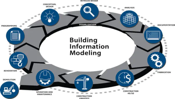
BIM is an acronym for Building Information Modeling. BIM is a new-age process used by architects, engineers, and construction professionals to design and construct buildings and infrastructure more efficiently.

CAD and BIM files have different uses and differ in many ways. You cannot replace one with another. To know the difference let’s understand the concepts in details.

 What is CAD and who uses CAD?

CAD is a highly decorative program that is used in the creation of making 2D drawings and 3D models using computer systems. The 3D AutoCAD CS software has been used by these engineers for decades helping them to design and manufacture complex products efficiently and effectively saving a lot of time.

CAD was developed back in 1963 by Ivan Sutherland that broke new ground records in 2D and 3D modeling and visual simulation. Engineers could directly draw on a CRT with the use of a light pen.

CAD programs are widely used by engineers in civil engineering and plant design in various industrial and manufacturing companies. These widely used computer software programs can help you explore and design ideas through photorealistic renderings and simulate how a design performs in the real world

Advantages of CAD

  • Easy to use, edit designs and modify drawings using computer-aided software
  • CAD models offers improved accuracy over manual drawings.
  • When a certain part or aspect of the drawing is required, duplication of labour is removed as everything is available and reproducible digitally
  • CAD software has a paper trail to refer back to automatically for any digital design you make

Disadvantages of CAD

  • May cause complacency as designers slip into the same design from their library each time and cause your designs to look the same
  • CAD allows different aspects of design to be put together but leaves out the bigger picture and the real-world issues of the design when doing so

What is BIM and who uses BIM?

BIM is an advanced 3D model-based program mainly used by architects, engineers, and contractors to design and build commercial buildings and infrastructure. With the help of BIM files, you can analyze and evaluate design decisions before starting the project.

BIM works as a single communication channel between work process and technology to work on the project collaboratively and efficiently. BIM is a digital 3D model based representation and shared resource that can be used by multiple parties involved in the design and build the structure from the beginning till the end.

This 3D model-based representation makes itself a cost-efficient and time-saving process and the chances of making errors are minimal and if any, that can be discovered at an early stage. BIM model provides data that can span the operation and management aspect of the construction project, and this information is later available to the structure owners as well.

Nowadays BIM is being commonly used by manufacturing engineers and contractors to provide a piece of detailed product information in different BIM formats. BIM software tools (the most common one being Revit) have redefined the design and construction workforce amongst the architectural and engineering design firms as well as contractors.

To know more about BIM modeling and using BIM solutions to make your construction project efficiently smoother, reach out to us at Monarch Innovation.

Advantages of BIM

  • Teamwork is enhanced as communication across all construction phases and techniques is coordinated
  • Any change made to the design either individually or simultaneously by different team members is dynamically shown and monitored
  • Even at the planning stage, the final structure or its components can be visualised
  • Any clashes between different sets of data in regards to components or between contractors can be identified and sorted before any cost is incurred in reversing the change.

Disadvantages of BIM

  • BIM software requires initial software investment and powerful PCs for processing
  • Staff and engineers need to be trained in BIM to make full utilisation of its features across projects
  • Although it might now sound like a big deal trust and change in work culture is a big issue for various teams working collaboratively on the project to make the most of their data. All parties need to be willing to share the data and invest in understanding its importance
  • The client often has no idea of the superior features of BIM modelling and don’t utilise the information presented by BIM to the full extent, wasting the time and effort of the construction team

CAD usage and How Does It Compare To BIM?

CAD models have been useful for a long time to help the architect to understand and render the modifications, development and optimization of the entire construction process. CAD has replaced manual drafting and helped the engineers, architects, and construction managers in creating designs in either 2D or 3D models so that they can visualize the construction of the project.

With the help of CAD now it is easier to make more accurate representations and modify them to improve design quality. It also helps the subcontractors to add up more details to the model.

Nowadays you can create a backup of your drawings and plans in the cloud storage which can be easily accessible by the contractors to CAD-based drawings/plans at the worksite making plan out the modifications easily. It also helps to identify the possible impact the changes might have on construction and adapt as needed and improves communication. This ultimately increases productivity and the effective utilisation of information.

Designers can now create more comprehensive designs considering other elements like electricity, plumbing, structure etc. which has only been possible with the help of CAD. This ultimately enables fewer work changes and a reduction in errors. The technological impact of CAD has been a game-changer in the industrial markets transforming construction into a technology job.

Many Engineers and contractors have been anticipating that these new-aged BIM software tools will become the focus of every new commercial building projects due to its collaborative process that allows architects, engineers and other constructional professionals to construct or design within a single 3D model.

One of the largest upgrades on BIM software from previous CAD software is that BIM allows work in 5 dimensions – time, cost, length, breadth and width. CAD allows work in only length, breadth and width. One can easily understand how this is a game-changer in the construction industry across project teams.

Today’s architects and engineers rely on BIM software to build and design 3D models of their buildings and infrastructure. The power of visualizing something in 3D gives the design and construction team a pretty accurate estimate of what the final structure should look like as well as the cost estimations along the way.

BIM Vs CAD – Which to Use?

CAD is mainly used for industrial design of mechanical and electrical work such as aeroplanes, mobile phones etc. On the other hand, BIM is used in the design and manufacturing of buildings and infrastructure such as airports, schools, hospitals, etc., and has become the most preferred software in the industrial markets. These files also give you the feature to detect virtual collision and construction-related errors before starting the actual work.

BIM models are designed for flexibility i.e., you can zoom in and zoom out and make a detailed design of your building. CAD is more likely a static, high-detailed component that has only one visual representation. A changeable BIM model will enable the CAD file to be viewable in its original form with full detail up to a definite zoom level.

Converting CAD files to BIM file types can result in blurring of CAD components while adjusting the scale of the model whereas adjusting the scale further can cause the image to discolor, appear as a black splotch, or fade from the screen. Hence CAD files fail to self-correct these adjustments when they are incorporated into BIM files.

CAD to BIM conversion – what are the advantages?

Although CAD has ruled the roost for a long time, it is now time to hand over the throne to Revit BIM models, which offer a far larger set of advantages. A lot of CAD designs are being converted to BIM models for high-rise or large scale construction projects because:

  • BIM models are more detailed, provide more options for analysis and deconstruction of the data.
  • BIM allows work in 5 dimensions – time, cost, length, breadth, and width. CAD allows work in only length, breadth, and width.
  • BIM models are easier to manipulate and use to incorporate new changes and design integrations.
  • Revit is a software that is now widely used, making it easier to communicate between stakeholders and project teams.
  • BIM models help in scheduling the timeline of the construction stages, estimating the cost, and billing the quantities of each component
  • BIM modeling can cover the whole lifecycle of the project – right from the design conceptualization to construction to demolition.
  • As all the information is pooled at a common spot and changes can be made dynamically, it dramatically reduces the loss of information across the pipeline, and increases efficiency.

To make your project lifecycle come alive with BIM solutions, reach out to Monarch Innovation and let our professional team of consultants and construction experts handle your challenge.

For more information, contact at info@monovative.com Or Call on +91 9974852647

Previous Next
Close
Test Caption
Test Description goes like this
Add to cart
Open chat
Hello,
Welcome to Monarch Innovation!

How Can I Help You..?