
Harsh Joshi
Co-founder & Technical Director
Zero clashes in the model, problems on site. Here are the seven gaps that let coordinated MEP models fail during installation, plus a readiness checklist and sign-off questions.
The coordination report says zero clashes. Everyone signs off. Three weeks into rough-in, the sheet metal crew finds a problem. Once insulation and hangers go on, the main supply duct will not fit under a transfer beam. The pipefitters then discover their sprinkler main blocks the only access to a fire damper. Nothing in the model clashed, yet the ceiling still has to be redone.
This happens because MEP clash detection only checks the geometry and rules it is given. A zero count tells you the tests passed, not that the building can be installed. This guide covers the seven most common reasons a clash-free model fails on site. It also shows how to check that a model is ready for installation, and what to ask your team before sign-off. If you need a refresher on the process itself, our page on MEP clash detection and resolution services covers how federation, testing and resolution work.
A zero-clash MEP model can still fail on site because clash detection only tests the elements, rules and tolerances someone set up. Insulation, hangers, access zones, install sequence, as-built structural deviations and late design changes often sit outside those tests. Treat "zero clashes" as one input to installation readiness, not proof of it.
What Does MEP Clash Detection Actually Check?
MEP clash detection is the process of combining all discipline models into one federated model and running automated tests to find conflicts. Those models usually cover mechanical, electrical, plumbing, fire protection, structure and architecture. Tools such as Navisworks Manage and Solibri run those tests and produce a list of conflicts for the team to resolve.
Most teams test for three kinds of conflict. The software is good at the first, partly reliable on the second, and blind to the third unless someone adds schedule data.
| Clash type | What it flags | What it usually misses |
|---|---|---|
| Hard clash | Two elements occupying the same space, such as a pipe passing through a beam | Anything not modeled, such as insulation, hangers or bracing |
| Soft (clearance) clash | An element inside a buffer zone set around another element | Clearance zones nobody defined, such as maintenance or code access |
| Workflow (4D) clash | Conflicts in install order or site logistics when linked to a schedule | Everything, if the model is never linked to the sequence |
That gap between what is tested and what is built is where most site problems start. Good MEP BIM coordination closes it by treating clash detection as one step inside a wider coordination process, not the whole process.
Seven Reasons a Zero-Clash Model Still Fails on Site
The clash matrix left gaps
A clash matrix defines which systems are tested against which. If ductwork was never tested against cable tray, or plumbing against ceiling grid, those pairs cannot produce clashes. The report reads zero because the question was never asked.
Gaps often appear when a discipline joins late, such as a fire protection or low-voltage model added after the matrix was set. Review the matrix every time a new model enters the federation.
Tolerances and approvals hid real conflicts
In MEP clash detection, teams set tolerances to filter out noise, such as a pipe touching a wall by a few millimeters. Set too loosely, the same tolerance also hides tight fits that crews cannot install. A related problem is the "approved" status. When clashes are approved as acceptable without a recorded reason, a real conflict can quietly leave the open list.
Ask for a breakdown of approved clashes, who approved each one, and why. Zero open clashes means little if hundreds were approved in bulk.
The model was missing what crews actually install
Clash software can only test the geometry in the model. Many MEP models are built at a level of detail suited to design, not installation. Typical missing items include:
- Duct and pipe insulation thickness
- Hangers, trapeze supports, seismic bracing and threaded rod
- Flanges, couplings, valve bodies and valve handles
- Drainage pipe slope over long runs
- Cable tray fill and conduit bend radius
- Equipment connections and flexible ductwork
The BIMForum Level of Development Specification describes how model content and reliability grow from LOD 300 to LOD 350 and LOD 400. For installation coordination, the elements that compete for ceiling space generally need LOD 350 detail, including supports and connections. Detailed MEP 3D modeling with real insulation and support geometry turns hidden conflicts into visible ones.
Clearance and access zones were never modeled
Some of the most expensive site problems are not collisions at all. Picture a valve that cannot be turned, a filter that cannot be pulled, or a damper that cannot be reached. Nothing overlaps, yet each one fails inspection or maintenance.
These problems only show up if clearance zones exist in the model as objects. Examples include access boxes in front of air handling units and working space in front of electrical panels. In the United States, the National Electrical Code (NFPA 70) sets minimum working space in front of electrical equipment. That space must exist in the model before software can protect it.
The building was not built where the model says
The model assumes perfect structure. Real concrete, steel and slabs vary within construction tolerances. Slab edges move, beams deflect, embeds shift and sleeves land in slightly different places. A duct coordinated with 25 mm of space can lose that margin entirely.
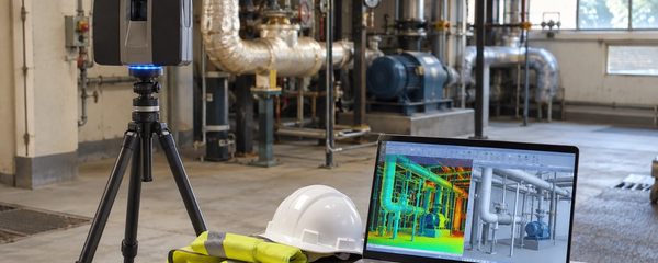
Renovation and expansion projects add another risk: existing conditions that never matched the record drawings. Laser scanning the structure or existing building and comparing it with the model before fabrication catches these deviations. Monarch Innovation's dimensions and reality capture services turn point cloud data into as-existing models for exactly this check.
The install sequence was never checked
A model can be geometrically perfect and still impossible to build in order. Say the duct main must go in first, but the electrical crew arrives earlier and runs cable tray at the same height. Someone now has to remove work. Prefabricated racks and spools raise the stakes, since they need clear lifting and installation paths.
Workflow clashes only appear when the model is linked to the construction schedule. A 4D review, part of virtual design and construction services, shows whether each trade can reach its space in the planned order.
The model and the site drifted apart
Coordination freezes a moment in time. After that, RFIs get answered, owners request changes, and approved equipment submittals replace basis-of-design units. A substituted pump or switchboard with a larger footprint can invalidate an area that was clash-free last month.
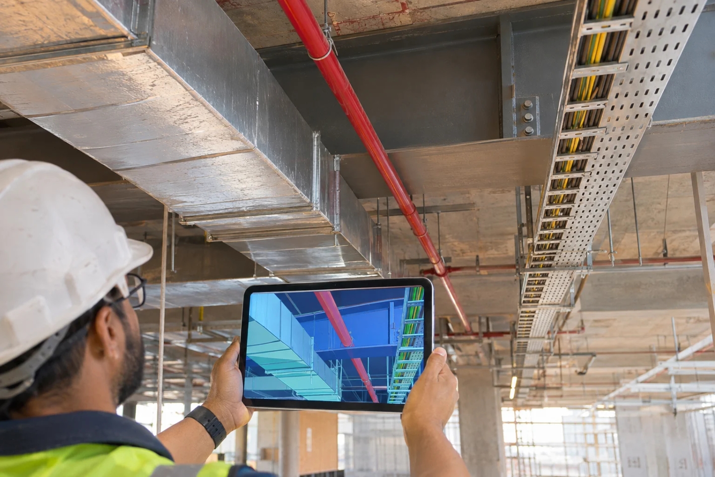
Drift also happens on the site side. Crews sometimes install from the original design drawings rather than coordinated shop drawings, or from a superseded model version. Issuing coordinated MEP shop and installation drawings from the approved model, with clear revision control, keeps the field and the model in step.
Zero Clashes vs a Construction-Ready Model
A construction-ready model and a model that passed MEP clash detection are not the same thing. The table below shows the difference.
| Factor | "Zero clashes" model | Construction-ready model |
|---|---|---|
| Clash matrix | Main disciplines only | Every system pair, reviewed when models change |
| Geometry | Design-level routing | Insulation, supports, bracing and fittings modeled |
| Clearances | Not modeled | Access, maintenance and code zones modeled and tested |
| Structure | Design model | Checked against scans or surveyed as-built data where needed |
| Sequence | Not reviewed | Install order and prefab paths checked against the schedule |
| Approved clashes | Bulk-approved | Each approval recorded with a reason and an owner |
| Field use | Coordination report only | Signed-off shop drawings issued by area and revision |
How to Check Whether a Clash-Free Model Is Ready for Installation
Before releasing an area for fabrication or installation, check what sits behind the MEP clash detection results. If any answer is "no", the zero count is not yet telling you the truth.
- The clash matrix covers every discipline model now in the federation.
- Clash tolerances are documented for each system pair in the BIM execution plan.
- Every approved clash has a recorded reason and approver.
- Insulation, hangers, supports and bracing are modeled in congested zones.
- Access and code clearance zones are modeled as objects and included in tests.
- Structure in congested areas has been checked against scans or survey data where risk is high.
- Install sequence has been reviewed against the schedule for that area.
- Approved equipment submittals have replaced basis-of-design equipment in the model.
- Each trade has signed off the coordinated layout for the area.
- Field crews have the current shop drawings, and old revisions are withdrawn.
Questions to Ask Your MEP Coordination Team Before Sign-Off
These questions take minutes in a coordination meeting. They show how much of the site risk your MEP clash detection process really covers.
- Which system pairs are in the clash matrix, and which were left out?
- What tolerance did you use for each test, and why?
- How many clashes were approved rather than resolved, and who approved them?
- Which zones were modeled at LOD 350, including insulation and supports?
- Where are maintenance and code clearance zones modeled?
- Have submitted equipment sizes replaced the design equipment in the model?
- Has the install sequence been checked for this area?
- How will site findings get back into the model?
The last question matters more than it looks. When site teams log issues directly against model elements, the coordination team sees problems while they can still be fixed. Our guide to construction QA/QC mobile apps with BIM sync explains how that field-to-model loop works.
Moving From Clash-Free to Install-Ready
MEP clash detection is still the best tool for finding conflicts before they reach the site. The mistake is treating its output as the finish line. A zero-clash model earns trust only when four things are true. The tests were complete. The model carried install-level detail. Clearances and sequence were checked. And the field built from the version the team coordinated.
Monarch Innovation supports contractors and design teams across this whole chain. That covers federated models, clash testing, LOD 350 MEP modeling, reality capture, 4D review and coordinated shop drawings. Does your model look clean while your site keeps finding problems? The gap is usually in one of the seven areas above. It can be closed before the next area is released.
Is your clash-free MEP model ready for installation?
Share your federated model and coordination reports with Monarch Innovation. Our BIM engineers will review your clash matrix, tolerances, model detail and sequencing, and show you where site risk remains.
Discuss Your MEP Coordination Project