
Harsh Joshi
Co-founder & Technical Director
When a part is discontinued and the drawings are gone, the physical part becomes the specification. Here is the eight-step workflow for recreating it, from first checks to a validated first article.
To recreate an obsolete part with no drawings, you rebuild its specification from the physical part itself. Obsolete parts reverse engineering means measuring the geometry, identifying the material, working out what the part does in its assembly, and turning that evidence into a CAD model and drawing a shop can manufacture and inspect. The goal is a part that fits and works, not a copy of a worn one.
That matters most when a machine is down and the OEM is gone, the supplier has stopped making the part, or the only drawing was lost years ago. This guide walks maintenance, plant and engineering leaders through the full workflow, from checking whether the part is truly obsolete to validating the first replacement. It is the same process Monarch Innovation follows in its reverse engineering services for legacy and discontinued components.
Preserve the sample, define its function, capture the geometry, separate wear from design intent, identify the material, rebuild the CAD and drawings, choose a manufacturing route, and validate a first article before you order more.
What You Need to Recover When Reverse Engineering an Obsolete Part
A replacement part needs four things recovered, and only one of them is shape.
- Geometry. The dimensions, surfaces and features, captured by measurement or 3D scanning.
- Material. The alloy or polymer, its hardness, any heat treatment and any coating.
- Function. What the part locates, seals, carries, guides or protects, and which features control that job.
- A manufacturing record. A toleranced drawing, a controlled model and an inspection plan, so the next order does not start from zero.
Most failed replacement parts get the geometry right and miss one of the other three. A bushing can measure perfectly and still wear out in weeks if it is made from the wrong bronze.
Before You Scan: Confirm the Part Is Really Obsolete
Reverse engineering is not always the fastest fix. Spend an hour on these checks first, because each one can save weeks.
- Look for a superseded part number. OEMs often replace a part with a new number rather than discontinuing it. Distributors and the successor company can sometimes cross-reference it.
- Check whether it is a standard component. Bearings, seals, O-rings, fasteners, keys and many bushings follow published standards. Markings and a few measurements often identify a catalog equivalent.
- Search for surviving data. Old maintenance files, purchasing records, manuals, exploded views and former suppliers sometimes hold dimensions or even drawings.
- Check surplus and aftermarket sources. These can cover an urgent need while the long-term replacement is engineered.
If usable drawings turn up, CAD conversion and migration services can turn them into a modern 3D model at lower cost than measuring the part.
| What you find | Best route |
|---|---|
| A superseded or catalog part exists | Buy it and record the cross-reference |
| Old drawings or 2D CAD survive and match the part | Convert the drawings to CAD |
| Only the physical part remains | Reverse engineer it |
| The part keeps failing in service | Reverse engineer it, then improve the weak features |
How to Reverse Engineer an Obsolete Part in Eight Steps
Here is the full workflow at a glance. Each step is explained below.
- Preserve the sample and gather context.
- Define the part's function and critical features.
- Choose the right measurement or scanning method.
- Separate wear from design intent.
- Identify the material and its condition.
- Rebuild the CAD model and drawings.
- Choose a manufacturing route.
- Validate the first article before release.
Preserve the Sample and Gather Context
Treat the old part as evidence. Photograph it from every side before anyone cleans, cuts or measures it, and record any markings, casting numbers or supplier logos.
Collect what surrounds it too:
- the mating parts
- the machine model and serial number
- the operating load, speed, temperature and media
- how the part failed
A cracked flange and a worn bore point to very different engineering problems.
If you have more than one sample, keep them all. A second used part, or better still an unused spare, is the best tool for telling original geometry apart from damage.
Define the Part's Function and Critical Features
Before measuring anything, decide which features actually matter. In most parts, a small number of features control fit and function, and the rest can be modeled to sensible nominal values.
Critical features usually include bearing seats, bores and shafts, sealing faces, thread sizes, hole patterns that locate other components, and datum faces. Mark these on the photos so the measuring effort goes where accuracy counts.
Choose the Right Measurement or Scanning Method
The right capture method depends on the part's shape, size and accuracy needs. Simple prismatic parts rarely need a scanner. Complex castings rarely work with calipers alone. Most good projects combine two methods.
| Method | Best for | Limitation |
|---|---|---|
| Calipers, micrometers and gauges | Simple turned or machined parts, threads, bores | Slow on complex shapes, operator dependent |
| Coordinate measuring machine (CMM) | Precise bores, hole patterns, flatness and datums | Needs access to features, slower for freeform surfaces |
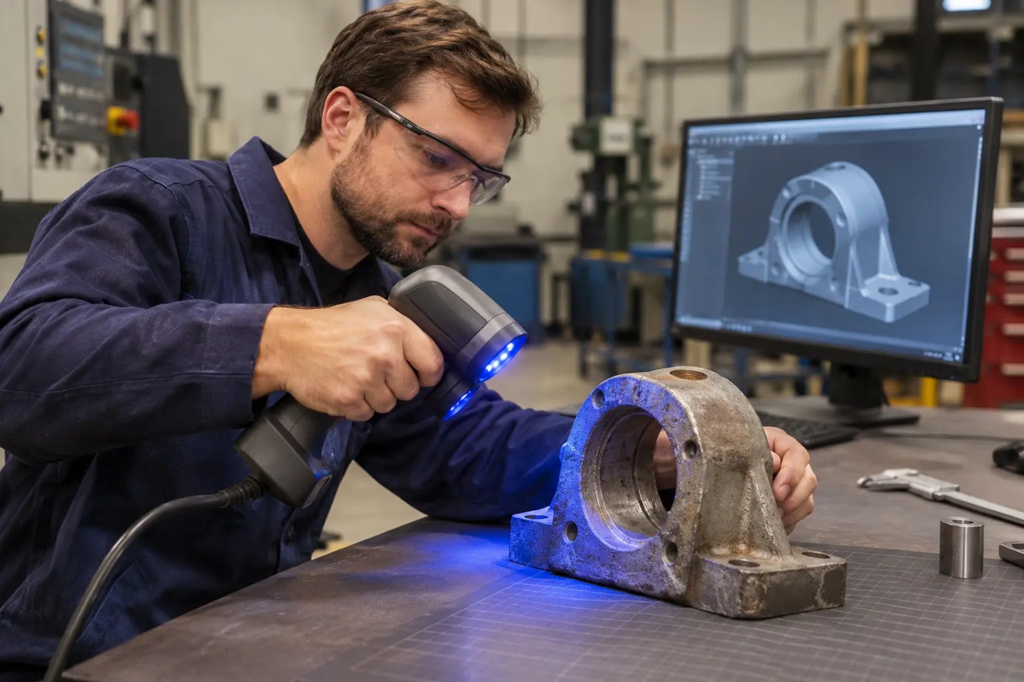
| Laser or structured light 3D scanning | Castings, molded parts, freeform surfaces | Shiny or dark surfaces may need coating, internal features hidden |
| Portable arm or on-site scanning | Large or installed components | Depends on site access and setup |
| Industrial CT scanning | Internal passages and hidden geometry | Higher cost, limited by part size and density |
A practical pattern is to scan the overall shape, then measure the critical features with a CMM or hand gauges and let those values control the model.
Separate Wear From Design Intent
This is where engineering judgment does most of the work. A part that has run for years has oval bores, rounded edges and eroded faces. Copy that into CAD and you manufacture the wear.
Engineers recover the original intent in a few ways:
- Compare worn and unworn areas. Surfaces that never touched anything often show the original size.
- Check the mating part. A shaft that still fits tells you what the bore was meant to be.
- Check against standard values. Original designs often use standard hole sizes, threads, fits and stock thicknesses in metric or inch units. A measured 24.97 mm bore may indicate a 25 mm nominal size, but confirm it against the mating shaft, unworn surfaces, expected fit and measurement uncertainty before assigning a nominal dimension.
- Compare multiple samples. Use two or more samples to identify consistent features and differences caused by wear. Do not automatically average worn dimensions. Use unworn surfaces, mating components and engineering judgment to infer the original dimensions.
Monarch Innovation's guide to reverse engineering cost explains how the choice between an as-built copy and a design-intent model also changes the quote.
Identify the Material and Its Condition
With no drawing, there is no material callout, so the material has to be identified from the part. Hardness testing shows the material's condition, but it cannot name an exact grade on its own. Chemical analysis identifies the alloy in metals, and polymer analysis does the same for plastics. Match the test to the material. For example, a standard handheld XRF analyzer cannot reliably measure carbon in steel, so spark OES or another suitable method is needed to confirm the grade.
Look beyond the base material. Many parts depend on heat treatment, case hardening, plating or a coating for their service life. The usual outcome is the closest standard, readily available grade, with any differences documented and reviewed by the engineer responsible for approving the replacement.
Rebuild the CAD Model and Drawings
The measured data becomes a clean CAD model built around nominal dimensions, not raw scan noise. A native parametric model is easiest to change later. A neutral STEP file lets any supplier open it.
The drawing is what makes the part repeatable. It should include:
- tolerances on the critical features
- GD&T where alignment matters
- surface finish
- material and heat treatment
- inspection notes
Proper technical engineering documentation under revision control is what turns a one-off rescue into a part you can reorder in five years.
Choose a Manufacturing Route
The way the part will be made can change the model. A machined part needs features a cutter can reach. A cast or molded replacement needs draft and consistent walls. A 3D printed part may need its orientation and material checked against the load.
For one or two urgent spares, CNC machining services or 3D printing services may be practical routes, depending on the part's material, geometry, load and dimensional requirements. For recurring demand across a fleet of machines, low-volume manufacturing can make batches without the cost of dedicated high-volume production tooling.
Validate the First Article Before Release
Do not order twenty parts from an unproven model. Check the CAD against the scan data, then make one part and inspect it against every dimension on the drawing.
That first article inspection confirms whether the drawing and the process produce the intended part. In aerospace, SAE AS9102C:2023 sets the requirements for performing and documenting first article inspection (FAI). It adds to customer, statutory and regulatory requirements rather than replacing them. Outside aerospace, apply the same idea at a lighter level. Measure the first part, test-fit it in the real assembly, and run it under representative operating conditions before releasing a batch.
When to Copy the Part and When to Improve It
Copy the part when it worked well for years and simply wore out. Improve it when it failed early, failed repeatedly or failed in the same place. A part that cracks at the same fillet every year has a design weakness, and an exact copy will crack there too.
Improvements are usually small and targeted: a larger fillet, a tougher material, a hardened surface, a better seal groove. Computer aided engineering (CAE) such as FEA can check the change before metal is cut. Keep the mating interfaces identical so the improved part still drops into the old machine.
Three Typical Obsolete Part Scenarios
These are illustrative examples of how the workflow changes with the part, not client case studies.
- A bronze bushing in an older hydraulic press. The geometry is simple and a CMM handles the bore and outside diameter. The real work is the material: the alloy and the running clearance decide whether the new bushing lasts.
- A molded plastic cover on a discontinued control panel. Snap fits, ribs and freeform surfaces call for 3D scanning and surface modeling. Low quantity points to machining or 3D printing rather than an injection mold.
- A machined bracket sold only inside an obsolete assembly. Nobody ever sold the bracket alone, so no part number exists to cross-reference. The hole pattern locates a motor, so the position tolerances on the drawing matter more than the outline.
Legal and Safety Checks Before Reproducing a Part
In the United States, the Defend Trade Secrets Act's definition of "improper means" expressly excludes reverse engineering and independent derivation. This does not create a blanket right to reproduce or sell every component. Patent rights, design protections, copyright in drawings, contractual obligations and other laws may still apply. The legal position depends on how the part was obtained, the rights attached to it and the jurisdiction in which it will be made or used.
Safety and regulation matter as well. Parts in aircraft, medical devices, pressure equipment or lifting gear may need approval before a non-OEM replacement goes into service. Check these questions with legal counsel and your quality team early, and treat this section as context, not legal advice.
Common Mistakes in Obsolete Parts Reverse Engineering
- Scanning a failed part and copying it exactly. The model inherits the wear, the crack and the distortion.
- Measuring without the mating parts. The new part matches the old one and still does not fit the machine.
- Guessing the material. Correct geometry in the wrong alloy fails early.
- Skipping tolerances on the drawing. Suppliers then pick their own, and two batches behave differently.
- Ordering in volume before a first article. One unchecked error is repeated across every part.
- Never filing the result. The model sits on one engineer's laptop until the next breakdown.
Planning for the Next Obsolete Part Before It Fails
Most obsolete parts are reverse engineered in a hurry, after a breakdown. A calmer approach is to find the risks first. List the parts on critical machines that have no drawing and no current supplier, rank them by downtime impact, and reverse engineer the riskiest ones while a good spare still exists.
The result is a digital spare parts library: controlled models and drawings you can send to any qualified shop when a part is needed. For plants running many older machines, sustaining engineering and legacy support treats this as one planned program instead of a string of emergencies.
Getting an Obsolete Part Back Into Service
Recreating an obsolete part with no drawings is an engineering task, not a scanning task. The scanner captures shape. Judgment recovers function, material and design intent, and validation proves the result before it reaches the machine.
Monarch Innovation combines 3D scanning and measurement with mechanical design, simulation, documentation and prototyping support, so one team can take a discontinued part from a worn sample to a validated replacement. If you have a part with no drawing and no supplier, contact Monarch Innovation with photos, its function and the machine it fits.
Have an obsolete part with no drawings?
Share photos of the component, any available dimensions or drawings, the machine model and application, the required replacement quantity, and details of its operating conditions if known. Monarch Innovation's engineers will review the information and recommend a suitable capture method, engineering deliverables and validation plan.
Discuss Your Reverse Engineering Project