How 3D laser scanning, as-built modeling, and clash detection reduce brownfield plant upgrade risk, rework, and shutdown delays, plus what to specify before commissioning a scan.

Harsh Joshi
Co-founder & Technical Director
A production line upgrade gets approved in March. The team plans it against drawings dated 2004. In September, during a shutdown window that cost real money to secure, a new skid arrives and does not fit, because a cable tray was rerouted in 2011 and nobody updated the drawing set. The crew loses two shifts to field modifications, and the plant restarts late.
That pattern repeats across process plants, factories, and power facilities every year, and it almost never comes from bad engineering. It comes from planning a physical change against a record of the plant that stopped being true years ago. In a brownfield environment, the building is the source of truth. The drawings are only a claim about it.
3D laser scanning for plant engineering closes that gap by capturing the facility as it exists today, then feeding that data into an as-built model that new equipment can be designed against and, where there is a defined operational use, into a digital twin. This guide covers how the workflow runs, what to specify before commissioning a scan, where the schedule and rework savings come from, and which mistakes turn a scan into an expensive file nobody uses.
Key Takeaways
- 3D laser scanning captures current plant geometry before retrofit, expansion, tie-in, or line-change design begins.
- An as-built 3D model turns scan data into engineering-ready information for layout, coordination, fabrication planning, and clash detection.
- Clash detection should cover more than hard collisions. Maintenance clearances, insulation allowances, access, lifting paths, and installation sequencing matter just as much.
- Scan scope should be tied to the use case, with accuracy, level of detail, coordinate control, coverage, deliverable formats, and data ownership agreed before fieldwork.
- A digital twin is not simply a point cloud or 3D model. It becomes useful when the model is connected to operational or asset information, has a defined owner, and is kept current.
Why Brownfield Upgrades Break on Existing-Conditions Data
Greenfield projects start with a blank site and a coordinated design. Brownfield projects start with forty years of undocumented change. Most operating plants carry some combination of the following:
- Drawings that were never updated after field changes. Every emergency repair, temporary bypass, and small capital project that skipped the drawing revision leaves a discrepancy behind.
- Multiple incompatible record formats. Original 2D paper drawings, scanned PDFs, partial AutoCAD files, and a 3D model built for one project ten years ago rarely agree with each other.
- Congested spaces with no measurable clearances. Pipe racks, conduit, ducting, and structural steel are often layered so densely that manual tape measurement is neither safe nor accurate.
- Restricted access during operation. Live process areas, hot work restrictions, and confined spaces limit how much a survey team can physically reach.
The financial consequence is concentrated in the shutdown window. Engineering rework during design is inconvenient. The same error discovered during a turnaround stops production. That asymmetry is the entire business case for spending money on accurate existing-conditions data before the design work starts, and it is why plant and industrial engineering teams increasingly treat reality capture as the first project activity rather than an optional survey line item.
What 3D Laser Scanning for Plant Engineering Actually Delivers
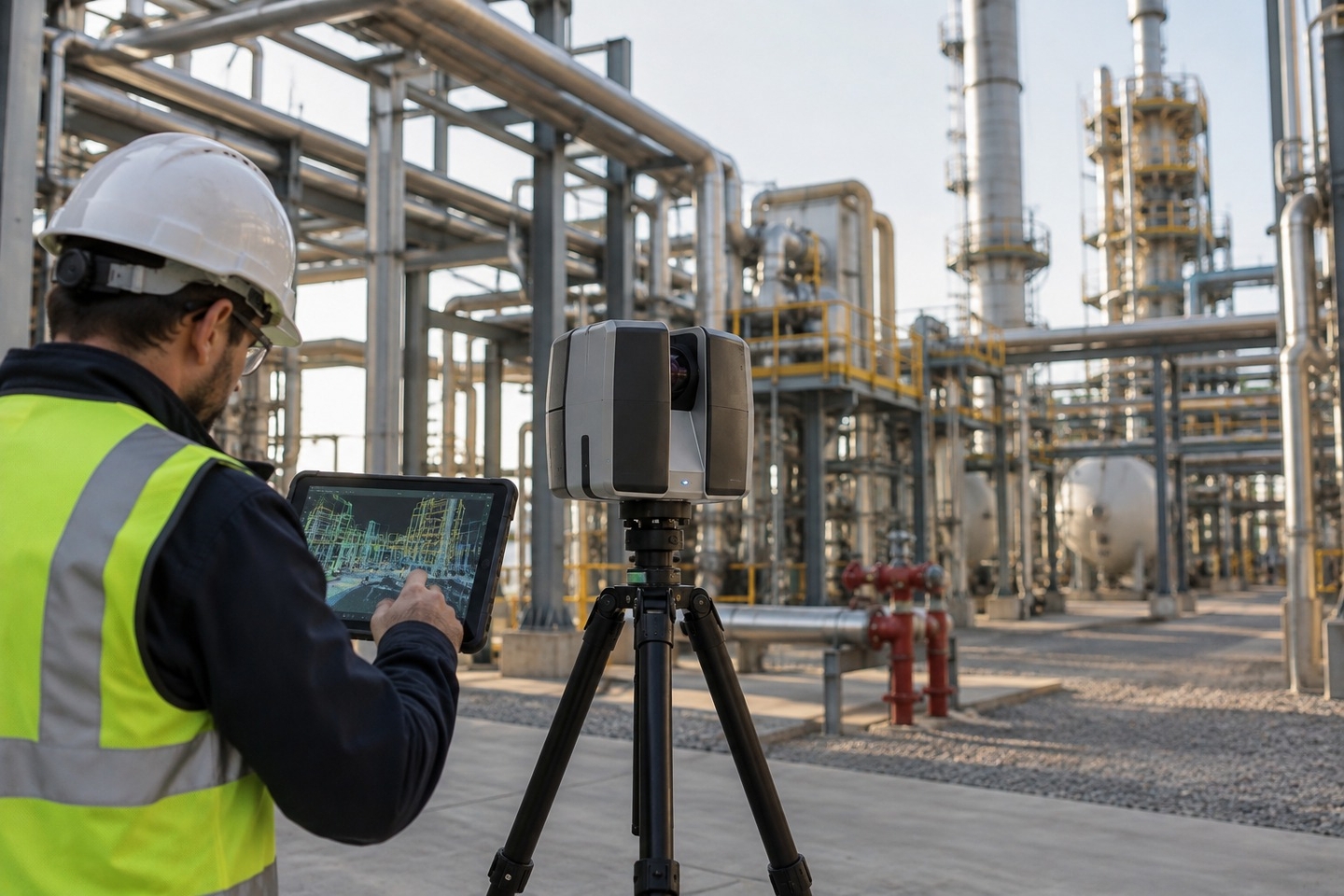
3D laser scanning for plant engineering is the use of terrestrial laser scanners or LiDAR systems to capture the current physical state of an industrial facility as a dense, dimensionally accurate point cloud, which is then converted into as-built drawings, 3D models, or BIM data that engineers can design against.
A scanner positioned in a plant records hundreds of thousands to millions of measured points per second, each with a spatial coordinate and usually a color value. Individual scan positions are then combined, or registered, into one coordinate system covering the surveyed area. The result is a measurable record of visible site conditions: two points in the scanned space can be dimensioned months later without returning to the field.
The main difference from conventional surveying is data density and reusability. Laser scanning records everything in line of sight rather than only the features a surveyor decided to capture, and the resulting dataset serves multiple disciplines and later design questions instead of a single deliverable. Subject to site safety rules, hazardous-area requirements, and access restrictions, scanning can often be performed while the plant keeps running, which matters when the whole objective is protecting production time.
From Point Cloud to As-Built 3D Model
A raw point cloud is measurement data, not an engineering model. It has no intelligence attached: a pipe in a point cloud is a cloud of dots shaped like a pipe, not an object that knows its diameter, material, or specification.
Turning it into something engineers can work with requires modeling. In point cloud to BIM and reality capture work, registered scan data is converted into as-built 3D modeling deliverables where equipment, piping, structural steel, and MEP systems exist as real objects with attributes. That model is what allows a designer to route a new line, check a clearance, or place a new skid with confidence.
Where Scanning Stops and a Digital Twin Begins
These terms get used interchangeably, and that causes scoping problems. They are not the same thing.
| Concept | What It Is | Primary Use | Changes Over Time? |
|---|---|---|---|
| Point cloud | Raw measured spatial data from the scanner | Verification, dimensioning, reference, clash checking | No, it is a snapshot |
| As-built 3D model | Intelligent objects modeled from verified site data | Design, coordination, fabrication, documentation | Only when updated or re-modeled |
| Digital twin | A model connected to operational, maintenance, asset, or sensor data | Operations, maintenance, simulation, planning | Yes, when the connected data and model are maintained |
A digital twin in a manufacturing or process context is a virtual representation of an asset or facility that is connected to relevant operational, maintenance, asset, or sensor information. The scan supplies verified geometry. The connected information and the update process are what make the digital representation useful as an ongoing operational resource.
For most brownfield upgrades, the practical sequence is: scan first, model second, connect operational data where there is a defined use case. A 3D model should not be labeled a digital twin simply because it represents the facility in three dimensions.
Who Should Use 3D Laser Scanning for Plant Upgrades?
3D laser scanning is most useful when an upgrade depends on reliable existing-conditions information. Typical stakeholders include:
- Plant owners and capital-project teams planning retrofits, expansions, and production changes.
- Plant, mechanical, piping, structural, and process engineers who need verified geometry for design and tie-ins.
- EPC, BIM, and VDC teams coordinating multiple disciplines around an existing facility.
- Maintenance, turnaround, and operations teams responsible for access, shutdown planning, installation, and future modifications.
The stronger the dependency on congested geometry, tight clearances, fabrication accuracy, or a limited shutdown window, the more useful current reality-capture data becomes.
Choosing the Right Level of Capture
Legacy drawings, manual measurement, and laser scanning are alternative ways to establish existing conditions. As-built modeling and a digital twin are not alternatives to scanning; they are the levels above it, built on the same captured data. The table below sets out that escalation.
| Level of Capture | Best For | Main Limitation |
|---|---|---|
| Legacy drawings | Facilities with well-maintained, recently verified documentation | May not reflect field changes or undocumented modifications |
| Manual measurement | Small, simple, accessible areas | Selective, slower, and difficult to reuse for later design questions |
| 3D laser scanning | Complex, congested, or poorly documented brownfield areas | Requires planning, registration, quality control, and site access |
| Scan plus as-built model | Design, coordination, fabrication planning, multi-discipline review | Higher modeling effort than a point-cloud-only deliverable |
| Digital twin | Ongoing operational, maintenance, planning, or simulation use | Requires connected data, ownership, and an update process |
The objective is not to replace every traditional survey method. It is to use the level of capture that removes the uncertainty that actually threatens the project.
The Workflow from Scan to Upgrade Execution
A well-run brownfield capture program follows a predictable sequence. Skipping stages is where most of the value leaks out.
- Define the use case and scope the capture. Decide what the data is for before anyone brings a scanner on site. A model for tie-in design needs different coverage and accuracy than a model for facility management handover.
- Plan scan positions around operations. Access windows, hot work permits, confined space entry, and shift patterns determine what can be captured and when. Good planning avoids gaps that only become visible after the crew has left.
- Capture and register. Field scanning is followed by registration, where individual scans are aligned into one coordinate system and checked against control points for accuracy.
- Model to the agreed level of detail. Only the systems in scope get modeled. Modeling every conduit in a facility when the project touches one production bay wastes budget without improving the outcome.
- Design the upgrade against verified geometry. New equipment, piping and equipment layouts, and structural modifications are developed inside the as-built model rather than against legacy drawings.
- Run clash detection and constructability review. Conflicts, access routes, and lifting paths are checked virtually before procurement commits.
- Rescan after execution. A short as-left scan documents what actually got built and becomes the trusted baseline for the next project instead of starting the decay cycle again.
How Clash Detection Protects the Shutdown Window
Clash detection for a plant expansion is the process of running the proposed new design against the as-built model to identify physical conflicts, insufficient clearances, and access problems before anything is fabricated or installed.
There are three categories worth checking separately, and teams routinely only check the first:
- Hard clashes. Two objects occupying the same space. A new pipe run intersecting existing steel.
- Clearance and soft clashes. Objects that fit but violate required maintenance access, insulation allowance, thermal expansion room, or code separation.
- Workflow and sequencing clashes. Whether the crane can reach, whether the module can pass through the door opening, whether a component can be removed later without dismantling something else.
The second and third categories cause most of the field surprises, because a design can be geometrically valid and still impossible to install during a live outage. Coordination tools such as Navisworks and Solibri can test all three when the model carries enough information, which is the same multi-discipline BIM coordination approach used on complex building projects, applied to process and production environments.
The value here is not that clashes disappear. It is that they get discovered in a design review meeting where the fix costs engineering hours, rather than at 2 a.m. during a turnaround where the fix costs production.
What to Specify Before You Commission a Scan
This is where brownfield scanning projects are usually won or lost, and it is what generic surveying vendors tend to leave vague. Before signing a scope, agree on the following.
Accuracy target. The U.S. Institute of Building Documentation publishes a Level of Accuracy specification that gives the industry a common language for how closely documentation must match physical reality. Set the target from the project use case. Fabrication tie-in zones need tighter control than a general layout model, and specifying maximum precision across an entire facility adds cost without improving the areas that matter.
Level of detail, by system. Accuracy and detail are separate decisions. Define which systems get modeled as intelligent objects, which stay as point cloud reference only, and which are excluded entirely.
Deliverable formats and data ownership. Ask for the registered point cloud in an open exchange format such as E57, the 3D imaging data exchange format specified in ASTM E2807, alongside any native files. That protects long-term interoperability, though you should still confirm exact formats, version requirements, and software compatibility before award. Confirm in writing that the point cloud, models, and drawings belong to your organization.
Coordinate system and control. Scan data needs to align with plant coordinates and any existing models. Agreeing on this up front avoids a painful re-registration exercise later.
Coverage assumptions. Be explicit about what will not be captured: obstructed areas, insulated runs, buried services, and anything inside an enclosure. Scanners record surfaces they can see, and that limitation should be documented rather than discovered during design.
What Drives the Cost of a Brownfield Capture Program
Costs vary widely by facility and scope, so treat any single figure you find online with caution. The variables that actually move the number are consistent:
- Area and congestion. Dense process areas need more scan positions per square meter than open warehouse space.
- Access constraints. Night shifts, permits, escorts, elevated work, and shutdown-only access all add field time.
- Modeling scope and detail. This is usually the largest single cost driver, and it is entirely within your control through scoping.
- Accuracy requirement. Tighter tolerances increase field, registration, and modeling effort together.
- Deliverable count. Drawings, models, format conversions, and documentation each add production time.
The comparison worth running is not scan cost against zero. It is scan cost against the cost of field rework, expedited fabrication, installation delays, and lost production time when existing-condition problems surface late. On a high-value shutdown, a small number of avoided site surprises changes the arithmetic quickly.
Mistakes That Waste a Scan Program
- Commissioning a scan with no project to consume it. Data captured as general good practice, with no design work waiting on it, sits unused while the plant keeps changing around it.
- Treating the point cloud as the deliverable. Handing raw scan data to a design team without a modeled interpretation moves the work rather than completing it.
- Modeling everything. Comprehensive facility models sound thorough and consume budget that would be better spent on tighter accuracy in the zones that matter.
- Ignoring the operations team. Maintenance and production staff know where the undocumented changes, access restrictions, and operational constraints are. Walking the area with them before scanning improves scope and coverage more than any equipment upgrade.
Making the Digital Twin Useful After the Upgrade
The upgrade is the reason to fund the capture. The twin is how the investment keeps paying out. Once accurate geometry exists, it can support several operational uses that were previously impractical.
Maintenance planning improves when technicians can review access and clearances before entering an area. Layout and capacity studies get faster because manufacturing and plant optimization work starts from verified dimensions rather than assumptions. Training and safety planning benefit from a walkable virtual environment, particularly for hazardous or restricted zones. And future capital projects begin with a current baseline instead of a fresh survey.
The condition for all of this is ownership. A digital twin needs a named owner, a defined update trigger, and at least one recurring operational use. Without those three things it reverts to a static model, which is the state most facilities are trying to escape.
A Practical Pre-Scan Decision Checklist
Before commissioning a brownfield scanning program, make sure the project team can answer these questions:
- What decision will the scan support? Tie-in design, equipment replacement, expansion, shutdown planning, documentation, or another defined use case.
- Which areas and systems are in scope? Define the physical limits and the disciplines that need modeled information.
- What accuracy is actually required? Set the target around the intended engineering or fabrication use rather than choosing maximum accuracy everywhere.
- What will the team receive? Agree on point cloud, model, drawing, report, and native-file deliverables before fieldwork.
- How will the data be maintained? Decide who owns it, when an update is triggered, and how future close-out scans get incorporated.
Answering these before the scanner arrives is what prevents a technically impressive dataset that does not solve the engineering problem.
Planning Your Next Plant Upgrade Around Verified As-Built Data
Brownfield upgrades do not usually fail on engineering quality. They fail because the design was correct for a plant that no longer exists in the way the drawings describe. Capturing the facility as it actually stands, modeling the systems that matter, and testing the new design against that model moves the discovery of problems from the shutdown window into the design phase, where fixing them is comparatively cheap.
Monarch Innovation works across both sides of this workflow, combining plant and industrial engineering with AEC and BIM solutions, including reality capture, as-built modeling, piping and equipment layout, and multi-discipline clash detection. That matters on brownfield work, because the scan, the model, and the upgrade design sit with one team rather than being handed between a survey vendor and an engineering contractor who each own only part of the outcome.
Schedule a Facility Assessment for Your Next Plant Upgrade
If you are scoping a retrofit, expansion, or line changeover and your existing drawings are not fully trustworthy, a focused assessment of your documentation and site conditions is a practical starting point. Speak with our plant engineering team to discuss scan scope, accuracy targets, deliverables, and how an as-built model could support your upgrade design and shutdown plan.
Frequently Asked Questions
What is 3D laser scanning for plant engineering?
3D laser scanning for plant engineering is the use of terrestrial laser scanners or LiDAR to capture visible existing conditions as a dense point cloud. The data can then be converted into as-built drawings, 3D models, or BIM deliverables so engineers can design retrofits, expansions, and tie-ins against current site geometry rather than relying only on legacy drawings.
Can a plant be scanned while it is still running?
Often, yes, subject to site safety requirements, access rules, hazardous-area controls, and line-of-sight limitations. Because laser scanning is non-contact, many accessible areas can be captured during operation. Areas behind guarding, inside enclosures, or otherwise inaccessible may require a shutdown or a separate access plan.
What is the difference between a point cloud and a digital twin?
A point cloud is a snapshot of measured spatial data. A digital twin is a maintained digital representation connected to relevant operational, maintenance, asset, or sensor information. Scanning supplies the geometric foundation, while the connected information and the update process are what make the representation useful over time.
How does clash detection reduce plant expansion downtime?
Clash detection compares the proposed design with verified existing conditions to identify hard conflicts, clearance problems, access limitations, and installation-sequencing issues before fabrication or installation. Finding those problems during design reduces late field modifications and removes much of the schedule pressure that comes from discovering them mid-shutdown.
How accurate does an as-built model need to be?
The required accuracy depends on the intended use. Fabrication tie-in zones generally require tighter control than general layout or reference models. The USIBD Level of Accuracy specification provides a framework for communicating documentation accuracy requirements. Define the target around the areas and decisions where precision genuinely matters.
What deliverables should a scan-to-model project include?
Typical deliverables include the registered point cloud in a suitable open exchange format such as E57, native model files in the agreed platform, as-built drawings for in-scope systems, a registration and quality report, and clear documentation of excluded or inaccessible areas. The exact package should match your design, fabrication, and handover requirements.
Is 3D scanning worth it for a small retrofit project?
It can be, especially when the work sits in a congested area, involves critical tie-ins, or depends on a limited shutdown window. The better comparison is capture cost against the potential cost of field rework, delays, and fabrication changes. For isolated changes in open, well-documented areas, conventional measurement may still be adequate.
How long does an as-built model stay accurate?
Accuracy begins decaying the moment field changes resume. Facilities that rescan affected areas at project close-out keep a trustworthy baseline for years. Those that do not typically find their documentation unreliable again within a few project cycles, which returns them to the position that made the first scan necessary.